CM602all_EJM8AESM_Service Manual.pdf - 第261页
Maintenance Adjustment Light Transfer-Head Assembly (3 nozzles) Remarks Item The offsets are entered into the screen below: Specifications: The newly measured offsets will be entered automatically into the screen at left…
Maintenance Adjustment Light Transfer-Head Assembly (3 nozzles)
Remarks
Item
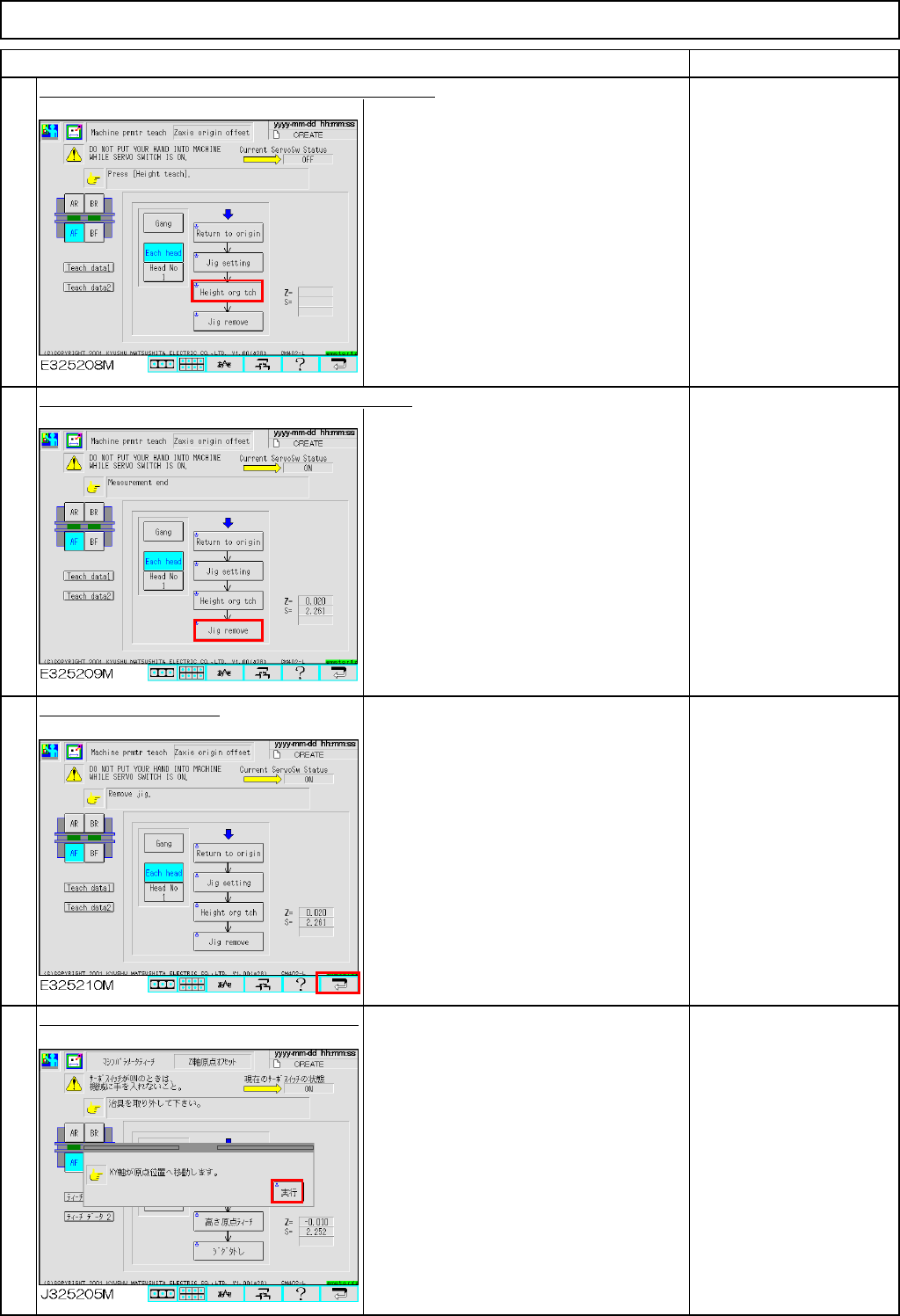
Press [Unlock] and [Height org tch] simultaneously.
The head camera moves to the heat
calibration mark of that stage and
measures the height of that nozzle.
Follow Steps 5 and 6 for
Head 1 to 3.
Press [Unlock] and [Jig remove] simultaneously.
The head moves to the nozzle set
position (over the NG box).
Remove Nozzle 1003.
Press the "Return" key.
To save the machine
parameter, press the
[Return] key.
Press [Unlock] and [Run] simultaneously.
The axes for the selected stage return to
origin.
13
14
15
16
EJM8A-E-SMA040303-A01-00
Page4-3-3-5
Maintenance Adjustment Light Transfer-Head Assembly (3 nozzles)
Remarks
Item
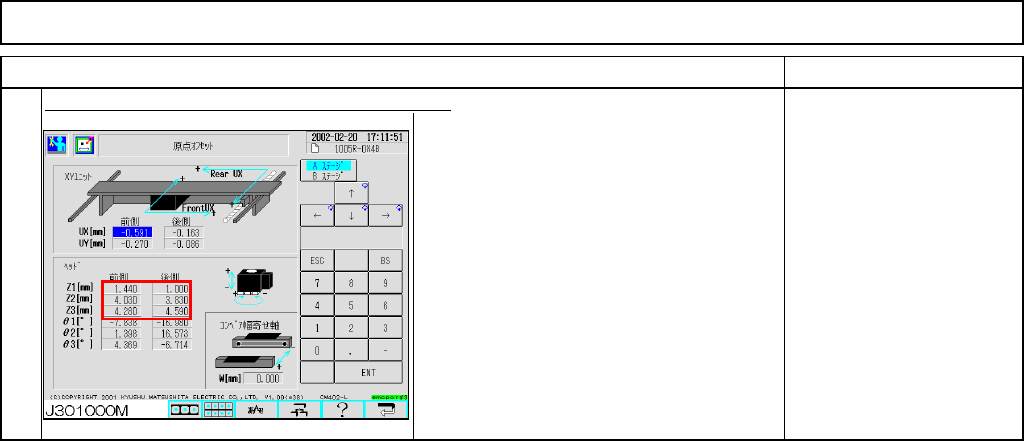
The offsets are entered into the screen below: Specifications:
The newly measured offsets will be
entered automatically into the screen at
left.
Offset range:
Z=1.00 mm to 11.00 mm
If an offset is out of the
specification, check that:
1. the vacuum pressure is
not excessively low.
2. the nozzle is not worn.
3. the nozzle is set
properly.
4. the vacuum sensor
functions properly.
17
EJM8A-E-SMA040303-A01-00
Page4-3-3-6
Maintenance Adjustment Light Transfer-Head Assembly (3 nozzles)
・Tools
None
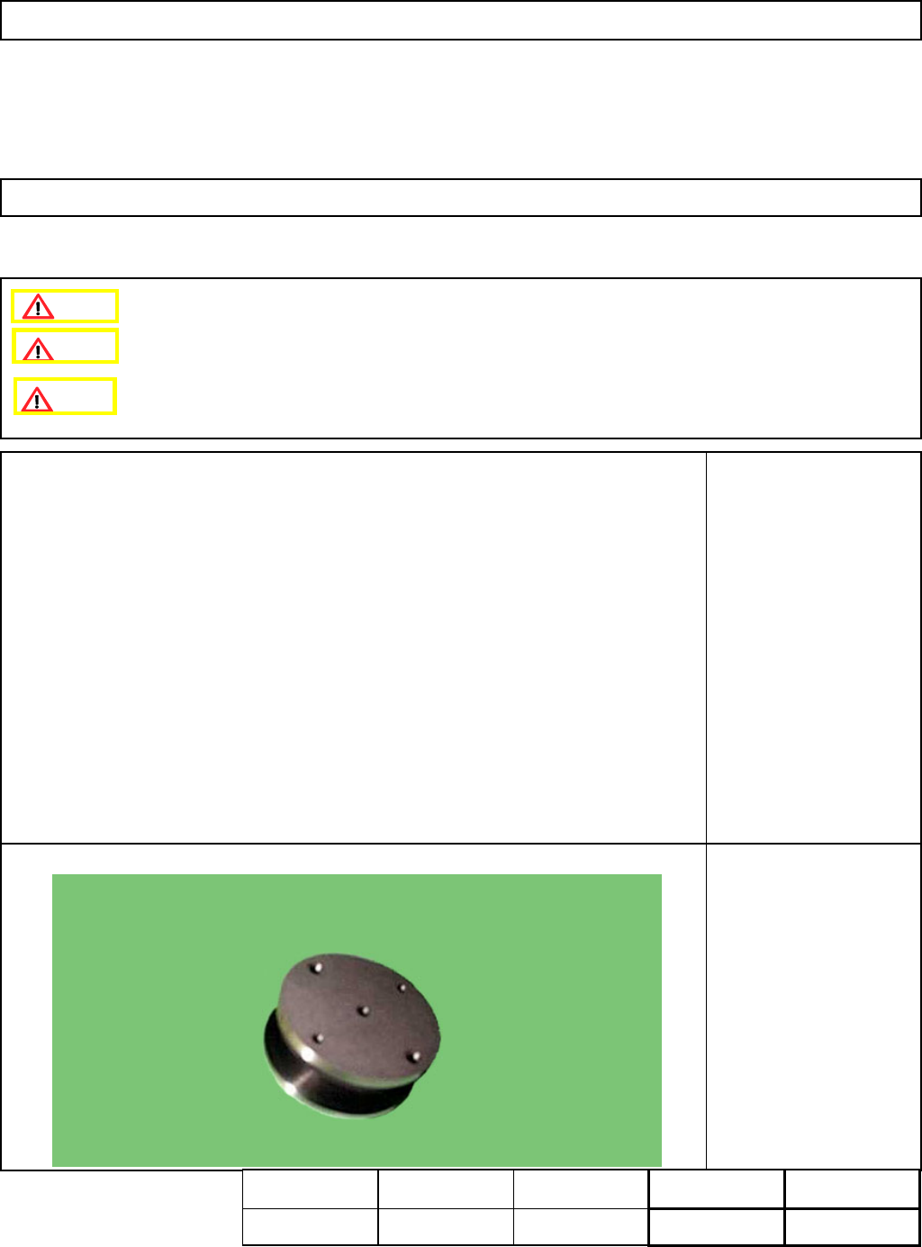
・Jig
5-hole Camera Teaching
Jig (For Multi-purpose
machines)
This section describes the procedures for entering the offset for the origin of the chip recognition camera theta axis.
4-3-4 Chip Recognition Camera --- Theta Axis Origin Offset
Remove the nozzle holders.
Remove the NG box.
Assembly
A
d
j
ustment
min.
Teaching
10min.
Total Time Weight of
Part
Removal
Disassembl
y
min.
10min. kgs
Caution
Dange
r
Warning
EJM8A-E-SMA040304-A01-00
Page 4-3-4-1