Smart Graphical User Interface (SmartG) Overview_rev1.pdf - 第55页
Copyright © ViT rox All Rights Reserved . Machine Setting (Inspection) Allows you to set how many error images are to be initially displayed on the Main Display Screen (Camera View area) after inspection errors are detec…
Copyright © ViTrox All Rights Reserved.
Machine Setting (Inspection)
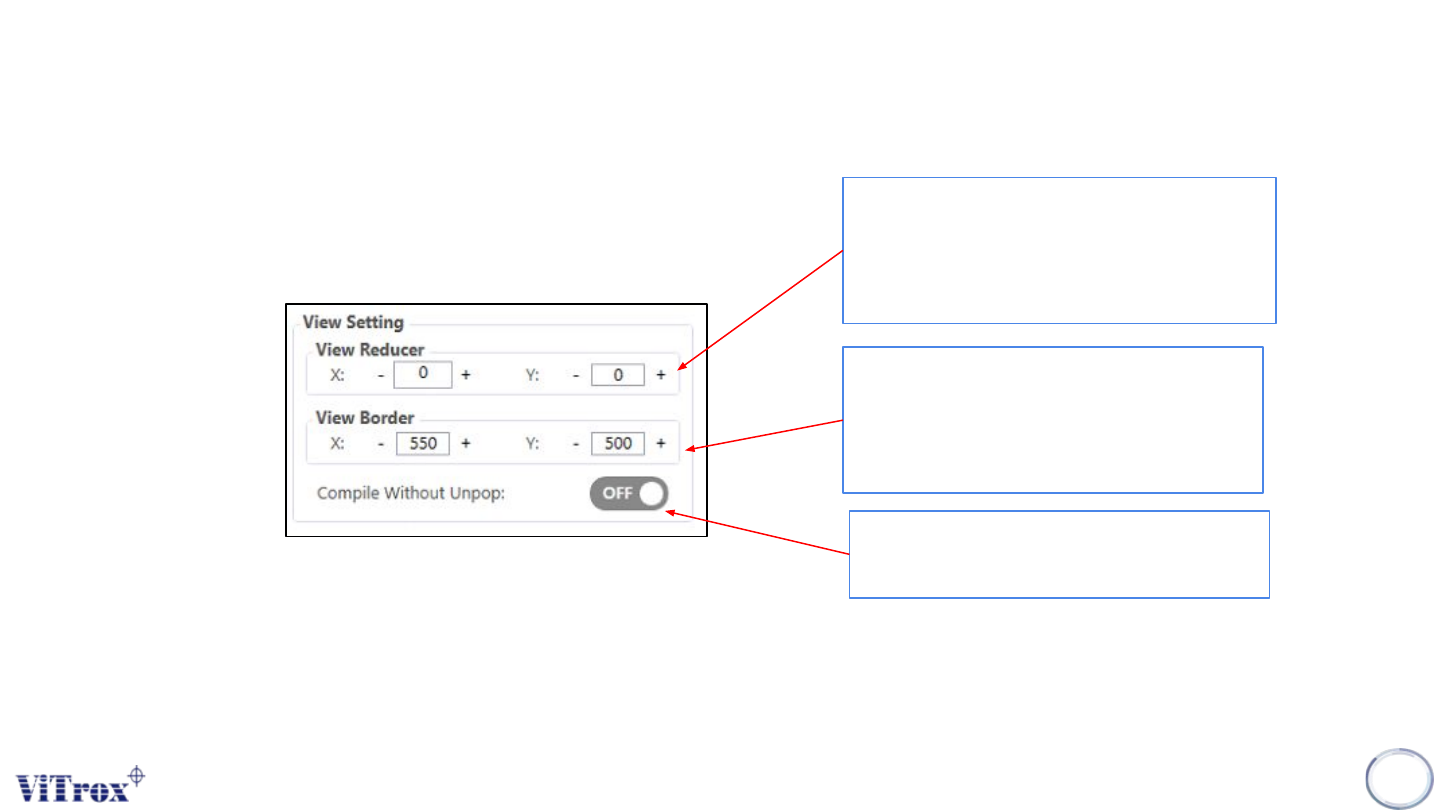
This increases or decreases the border
inside the camera field of view. A default
of 550 microns (X) and 500 microns (Y)
is automatically set.
54
This is similar to the View Border, but it is
only applied when considering whether a
component must be split into multiple
views. This is specified in microns.
To compile the program with/without
Unpopulated area feature
Figure 45: View Setting
Copyright © ViTrox All Rights Reserved.
Machine Setting (Inspection)
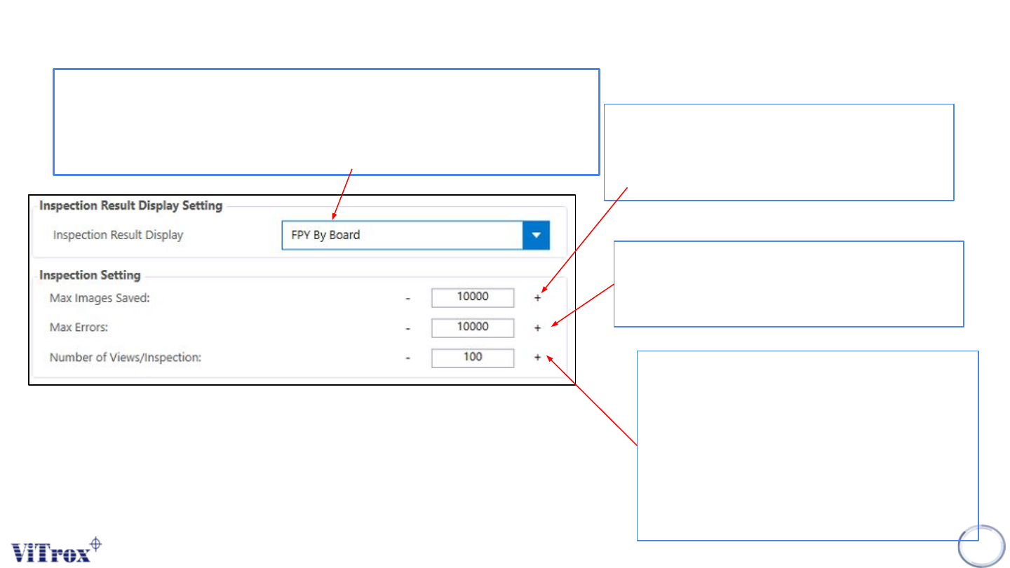
Allows you to set how many error images are to
be initially displayed on the Main Display Screen
(Camera View area) after inspection errors are
detected on a board. This is set to 12 by default.
55
Represents the maximum number of errors that
the Vitrox AOI machine can detect on a board
before the ViTrox AOI machine will abort the
inspection.
Displays the percentage of views permitted per
inspection. The default is 100., but you can set
this to a smaller value if you want to inspect
only a sample of each board in order to keep
up with an extremely fast production line. For
example, if you set this to 50, the system will
expect the first half and second half of
alternating boards.
Figure 46: Inspection Setting
FPY rate by board: Total Good Units/ Total Unit Produced
Eg.
Total Unit Produced: 1000 FPY %= (800-20/1000)
Total Good Units: 800 = 0.78%
Total Bad Units/ reworks: 20
Copyright © ViTrox All Rights Reserved.
Machine Setting (Inspection)
56
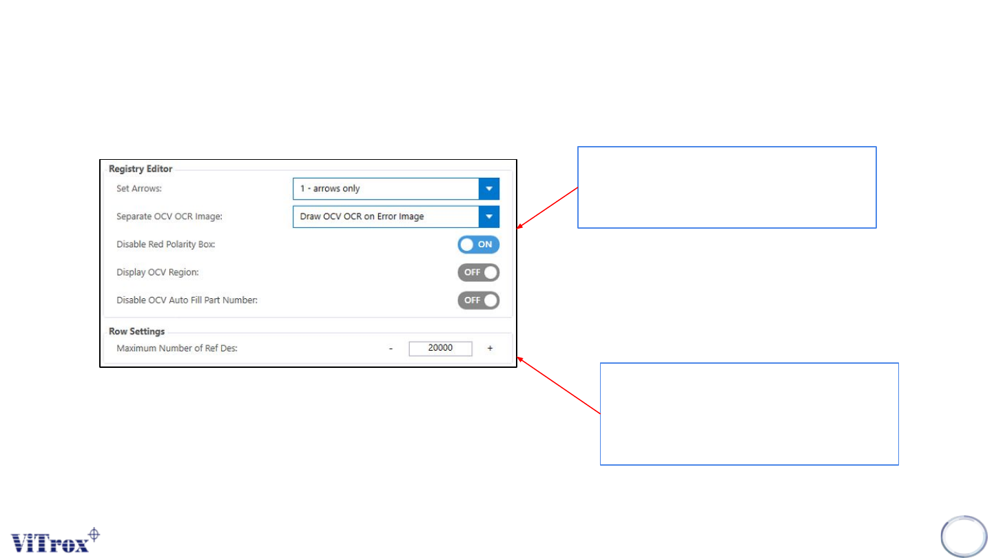
Figure 47: View Setting
User can configure the registry edit setting
to turn on the box display/drawn on defect
image.
Modify the number of row settings in
C:\CPI\data\config.txt in SmartG interface
to support the maximum number of ref
des in a program.