Smart Graphical User Interface (SmartG) Overview_rev1.pdf - 第65页
Copyright © ViT rox All Rights Reserved . Machine Setting (Calibration) 65 Sends the XY T able to its home position. In a standard V510 system the home position is at the back right-hand corner of the machine Sets the XY…
Copyright © ViTrox All Rights Reserved.
Machine Setting (Calibration)
64
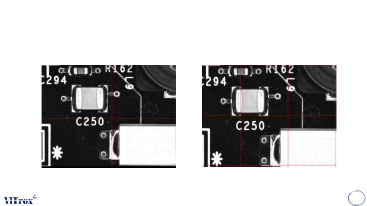
Figure 54: Crosshair View Figure 55: Gridlines View
Different of Crosshair and Gridlines
Copyright © ViTrox All Rights Reserved.
Machine Setting (Calibration)
65
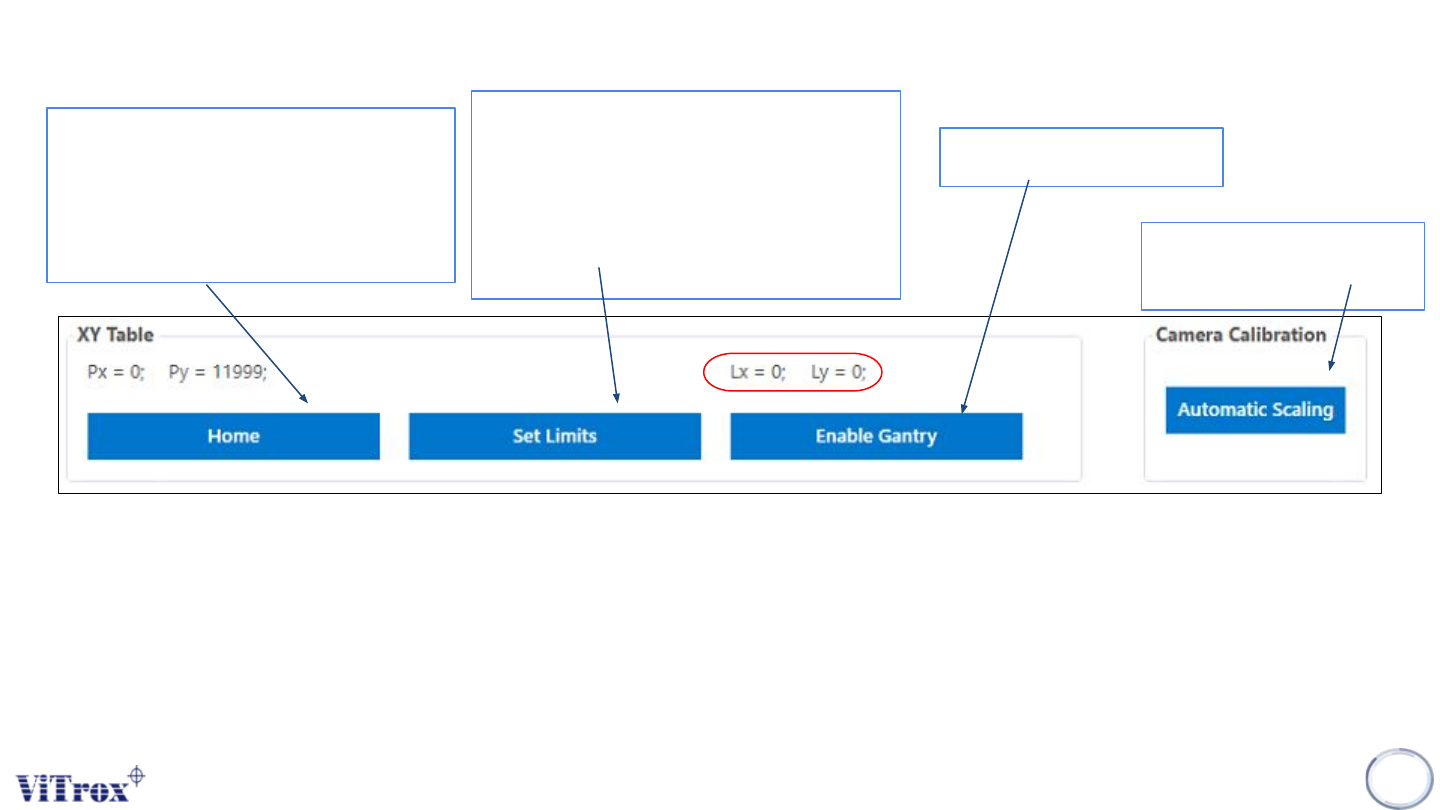
Sends the XY Table to its home
position. In a standard V510
system the home position is at the
back right-hand corner of the
machine
Sets the XY Table software limits,
which are a safety feature used by
the V510 system. These limits define
the operational area within which the
XY Table can be operated by
software.
Enables the XY Table
● This is the position of the gantry over the board, with respect to the given board. That is, when the system
inspects the fiducials, it understands where everything is in reference to the fiducials. This is the same frame of
reference as the PLX file, hence if you use the Insert à Ref Des feature, Lx and Ly represent the coordinates of
the inserted components.
Ensure the camera well
focusing
Figure 56: XY table and Camera Calibration
Copyright © ViTrox All Rights Reserved.
Machine Setting (Calibration)
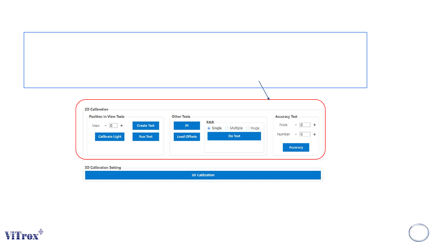
This should only be used in pre-reflow setup.This calibration is done to inspect components at different
positions in the camera's field of view. It calculates offsets to compensate for the curvature of the lens. It is
necessary to carry out this calibration to ensure that positional measurement is accurate.The Position In
View test should be done when pixel size is changed, lens is refocused, or lighting intensities change
significantly, or alternatively when an entire optical setup is due.
66
Note: 3D Calibration Setting to perform the calibration when the pixel size is changed, lens refocused or lighting intensities
change significantly and perform calibration maintenance.
Figure 57: 2D and 3D Calibration Setting