Smart Graphical User Interface (SmartG) Overview_rev1.pdf - 第64页
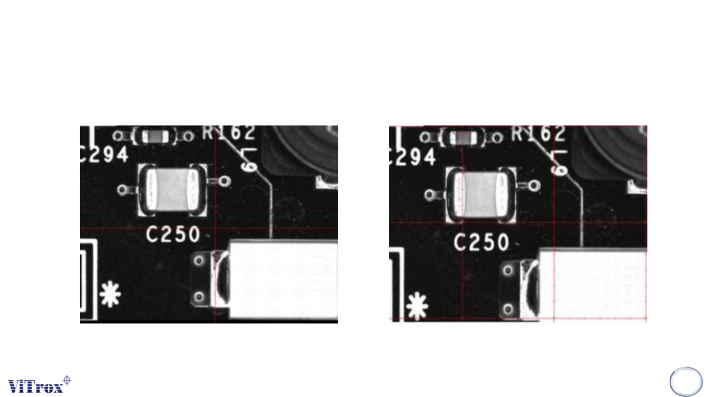
Copyright © ViT rox All Rights Reserved . Machine Setting (Calibration) 64 Figure 54: Crosshair View Figure 55: Gridlines View Different of Crosshair and Gridlines
Copyright © ViTrox All Rights Reserved.
Machine Setting (Calibration)
63
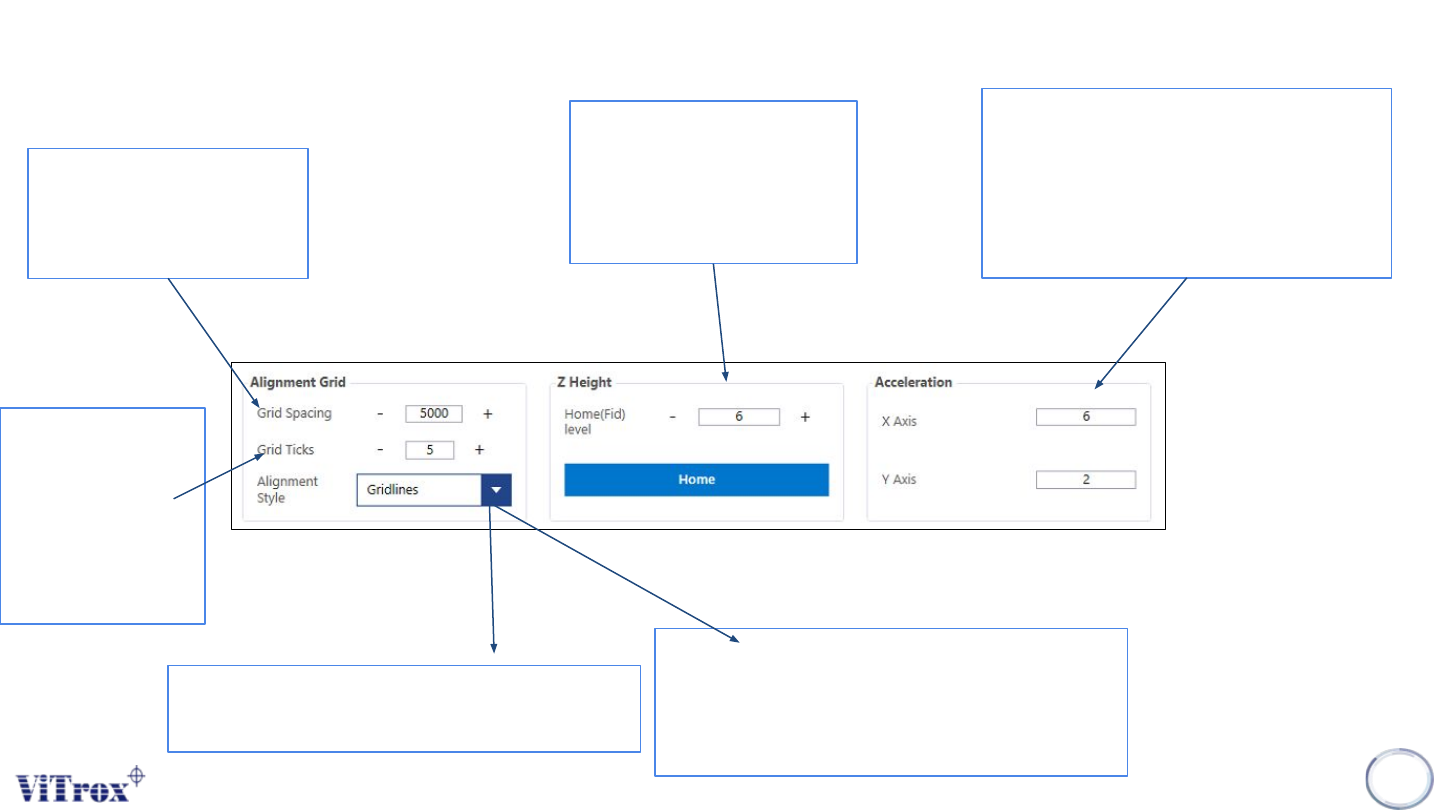
When Alignment Style is
set to Gridlines, this sets
the spacing between the
grids. This is set to 5000
by default
When Alignment
Style is set to
Gridlines, this
sets the number
of ticks between
each Grid. This is
set to 5 by default
Z height customization:
Recommended value: 6
Home: To make a default
of Z height
Sets the accelerations of the XY Table
in the X and Y directions in meters per
second. Recommended values for X
and Y are 3 and 1.5 respectively for
accuracy, and 6 and 2 respectively for
high speed.
Figure 53: Alignment Grid, Z height and Acceleration function
● Gridlines - This draws a series of
lines with ticks as determined by the
user specified Grid Spacing and Grid
Ticks parameters.
● Crosshair - This draws a single cross
hair through the centre of the display
Copyright © ViTrox All Rights Reserved.
Machine Setting (Calibration)
64
Figure 54: Crosshair View Figure 55: Gridlines View
Different of Crosshair and Gridlines
Copyright © ViTrox All Rights Reserved.
Machine Setting (Calibration)
65
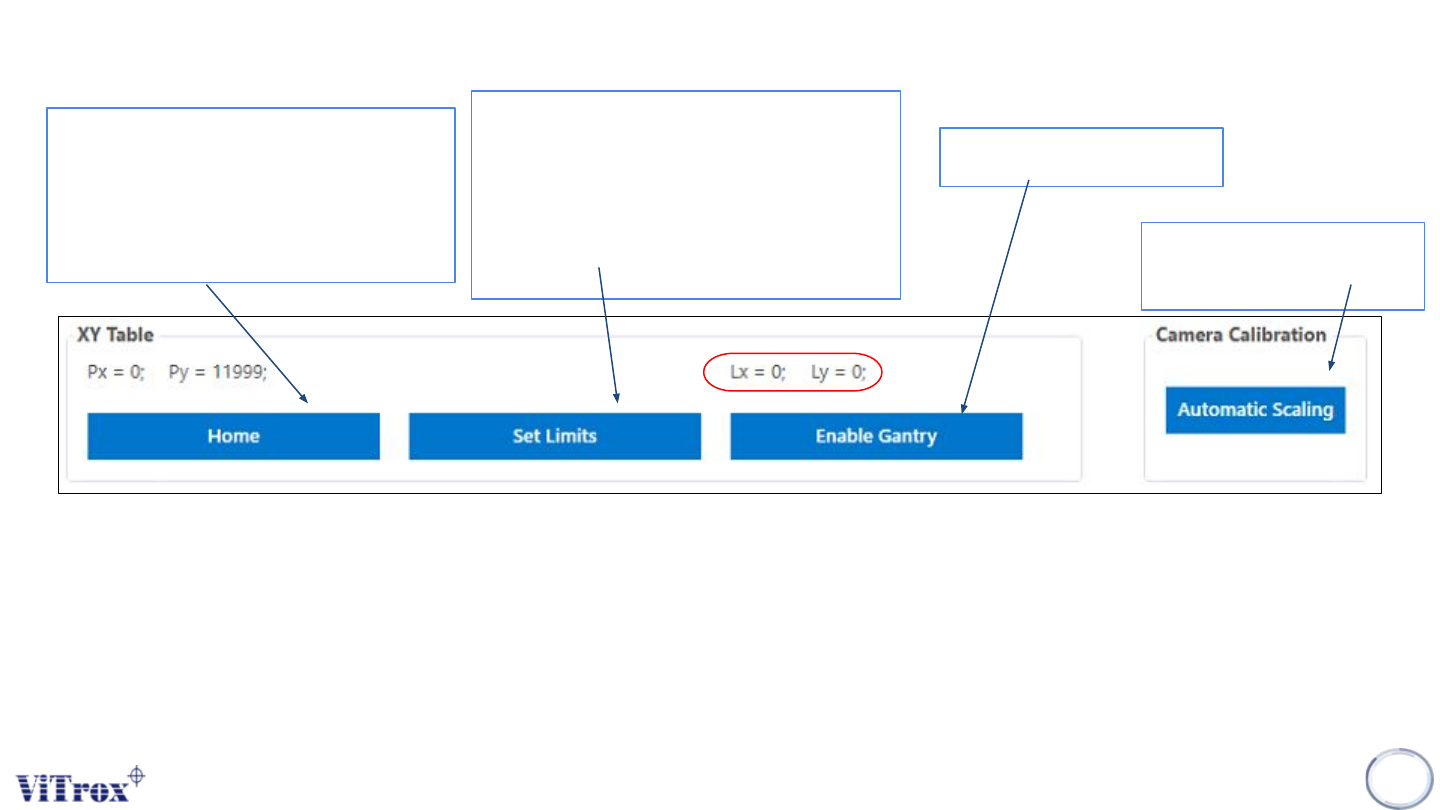
Sends the XY Table to its home
position. In a standard V510
system the home position is at the
back right-hand corner of the
machine
Sets the XY Table software limits,
which are a safety feature used by
the V510 system. These limits define
the operational area within which the
XY Table can be operated by
software.
Enables the XY Table
● This is the position of the gantry over the board, with respect to the given board. That is, when the system
inspects the fiducials, it understands where everything is in reference to the fiducials. This is the same frame of
reference as the PLX file, hence if you use the Insert à Ref Des feature, Lx and Ly represent the coordinates of
the inserted components.
Ensure the camera well
focusing
Figure 56: XY table and Camera Calibration