VI User Manual.pdf - 第101页
.TST file creation Vision 2007 4.10 User Manua l Rev 01 4 - 27 Multi-zones are use d for components that are bi gger than the came ra field of view. That is why even if only one zone is visualized on the tst file, severa…
.TST file creation
4 - 26 Vision 2007 4.10 User Manual Rev 01
4.8 Zones creation
4.8.1 Zones presentation
Zones can be created automatically by the menu or via the creation of the .tst file or manually.
Zones will be created with defaults values that are defined in Default.ini file. Each zone can have
its own properties and its own light levels. A zone can be created on any components even if it
is not executable (to create zones on only executable ones a flag must be set in the menu).
Zones are associated and
regrouped into zones layers
displayed in a small window
when the Display zones
menu is selected. Zones
may have different colors
as shown opposite.
4.8.2 Zones.dsc file and default values
Zones.dsc file is a structured file. The file memorizes the characteristics of the joker zones like
Jedec codification, centering property, light level settings, same for the centered zones (Jedecs).
This file will be used and shared by all the tst files. Zones.dsc file content is displayed during the
automatic zones creation for centered and Joker zones.
Default values are kept in the Default.ini
file that can be acceeded by the user.
4.8.3 Type of zone
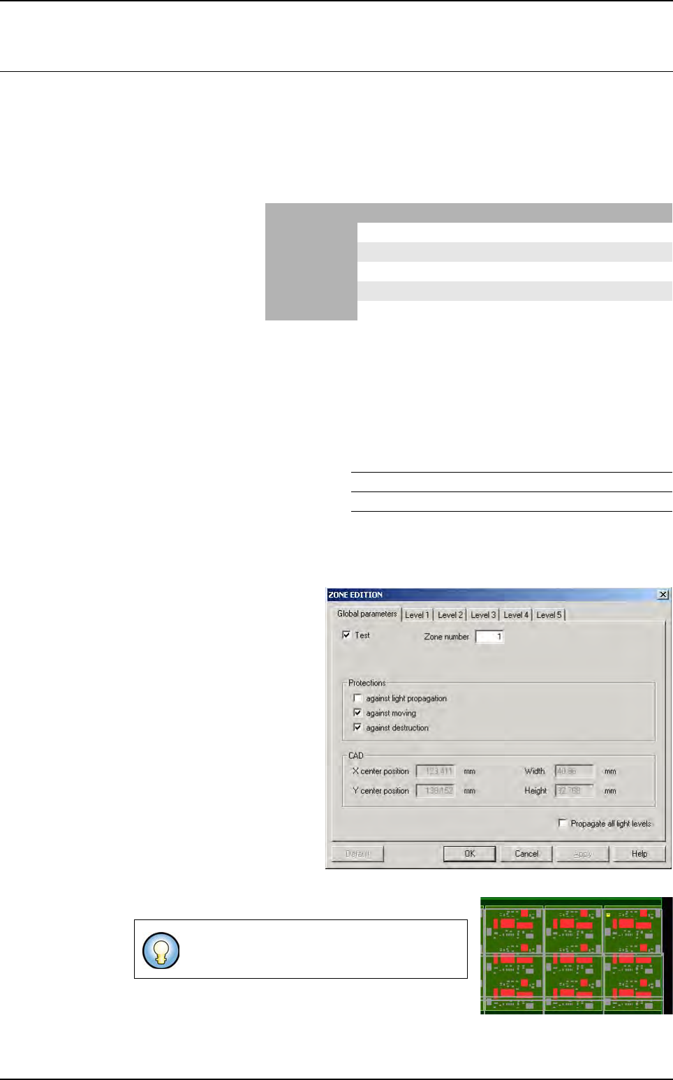
4.8.3.1 Standard zones
Standard zones can be created
on all the components except
very large ones that need multi-
zones. The user can check the
box
Propagate all light levels
if
he had modified light levels set-
tings. It will copy the 5 light levels
settings on all the standard zones
and multi-zones which are not
protected against
Light propa-
gation
. The
Default
button will
removed the light levels settings
modifications and set the default
ones that are defined in
De-
fault.ini
file.
Standard zones are defined by a continuous mauve line.
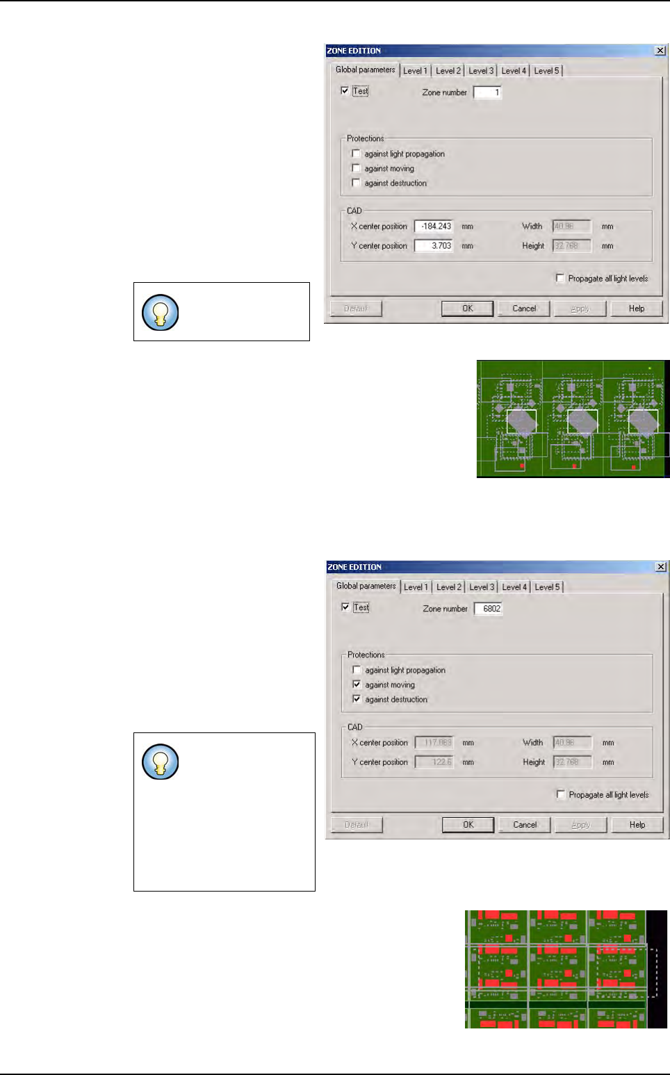
4.8.3.2 Multi-zones
By default, a standard zone is created without
any protections.
Standard/Centered Multi-zones Joker
In test purple white blue
Not in test Red Red Red
Protected dotted line dotted line dotted line
Not protected continuous line continuous line continuous line
Selected yellow yellow yellow
ZONE JOKER CENTERED ON JEDEC TRUE (value 1)
ZONE FILE PATH C:/VIT/CONFIG/
.TST file creation
Vision 2007 4.10 User Manual Rev 01 4 - 27
Multi-zones are used for
components that are bigger
than the camera field of view.
That is why even if only one
zone is visualized on the tst
file, several images are taken
into account during the exe-
cutions of the associated pro-
cesses. Multi-zones are
automatically created if very
large components are
present on the panel via the
Creation zones menu or via
the creation of the tst file.
The multi-zones are defined by a continuous white line.
4.8.3.3 Centered zones
Centered zones have been defined in order to center a component in the camera field of
view and in order to avoid the problems linked to the camera optical aberrations.
Centered zones get the same
properties as standard zones.
The only difference is that
these zones are by default
protected against moving and
destruction at their creation.
Centered zones allow one
centered jedec for one zone
plus others components with
different jedecs.
Centered zones are defined by a dotted mauve line
when the moving and destruction protection are set,
with a continuous mauve line when the protections
are removed.
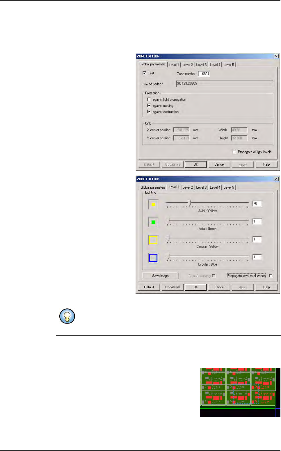
4.8.3.4 Joker zones
Multi-zones cannot
be manually created.
Pay attention to the
fact that the jedec
codification is not
displayed on the
creation window of
the centered zone
but it is saved in the
zone.dsc file.
Zones creation
.TST file creation
4 - 28 Vision 2007 4.10 User Manual Rev 01
The Joker zones have been defined in order to get additional lightings for some compo-
nents or type of components which generate problems with the inspection.
The aim is to affect one specific zone Joker zone to one family of component to be able
to re-use this configuration in different tst. files.
Joker zones can be identified
by the Linked Jedec name
that represents one or sever-
al jedecs codifications struc-
turing the name of the zone
and the “name” of the layer,
these jedecs have exactly the
same light levels settings.
Joker zones get the same
properties as centered zones.
Joker zones allow for one je-
dec specific light levels.
Joker zones are centered by
default, meaning that only the
selected jedec belongs to this
zone and this particular com-
ponent linked the jedec is
centered in the zone.
Update file button (activated when a level tab is selected) allows the update of the
zones.dsc file following to the user modifications concerning light levels settings (the up-
date is not automatic and concern only the selected tab).
Joker zones are defined by a dotted blue line when the
moving and destruction protection are set, with a con-
tinuous blue line when the protections are removed
(description board below).
If the joker zone is not centered on the jedec associated, only the components
with the same jedec or different
jedecs present in the zone .dsc file needing
the same light levels
and not centered, are affected to this zone.
Zones creation