VI User Manual.pdf - 第190页
Tools library 7 - 28 Vision 2007 4.10 User Manual Re v 01 7.6.2.2 BGA test Click on Test ( A ) button to apply all the inspection pa- rameters to the model. Score ( B ): score of the tested tool (rate of detection suc- c…
Tools library
Vision 2007 4.10 User Manual Rev 01 7 - 27
7.6.2.1 BGA parameters
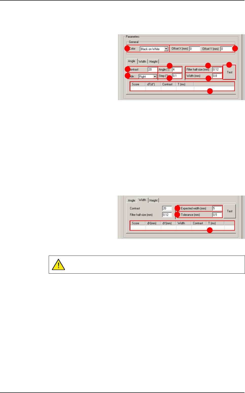
General section
Select the Color (A) of the
component to determine the
edge polarity.
If necessary indicate the Off-
set X & Y (mm) (B) from CAD
position.
Angle tab
Contrast (C): minimum contrast transition.
Side (D): side of BGA to test.
Angle (°) (E): search angle.
Step (°) (F): search angle accuracy.
Filter half size (mm) (G): filter half size of edge.
Width (mm) (H): width of turning edge.
Press Test ( I ) button to test the angle detection.
Angle test result (J).
Width & height tabs
The parameters are the
same for Width and Height
detection.
Expected width (mm) (K) of
the component.
Tolerance (mm) (L) on ex-
pected width.
Width or Height test result (M).
If you have not tested the
Angle
before,
Width
and
Height
are tested at 0°.
A B
E
C
F
H
G
I
J
D
L
K
M
BGA
Tools library
7 - 28 Vision 2007 4.10 User Manual Rev 01
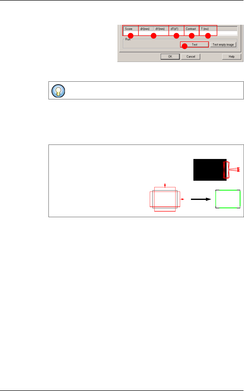
7.6.2.2 BGA test
Click on Test (A) button to
apply all the inspection pa-
rameters to the model.
Score (B): score of the tested
tool (rate of detection suc-
cess).
dX&Y(mm) (C): position in X and Y between the transitions (centre between the 2 tran-
sitions).
dT(d°) (D
): position result in theta of the tested model.
Contrast (E): difference of a transition, in gray level values between background bright-
ness and component brightness. This value is the average of the transition contrast
found during the test.
T (ms) (F): inspection time.
If only one transition is looked for, this is the position of the transition found.
Angle and postion detections
The BGA angle is detected by a turning edge. This edge re-
turns the angle that gave the best contrast in its search angle.
BGA position detection is returned by 2
double transition edges.
These 2 double transition edges return the
X and Y position of the BGA component.
A
B C D E F
Scoring by size
and contrast
BGA
Tools library
Vision 2007 4.10 User Manual Rev 01 7 - 29
7.7 SO or QFP model
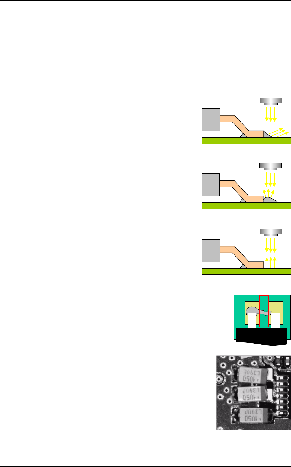
7.7.1 Joints detection
Joint inspection is the ability to check if there is solder or not. This tool does not consider quality. The
solder reflect few light to camera when the solder is good, and many when the solder is not good.
Histogram is used to perform joint inspection.
7.7.1.1 Good joint
With solder the reflection is out of the camera, which
causes a black area at the end of lead.
7.7.1.2 Bad joint
The curve of a bad joint weld reflects the major light
flux at the vertical of the solder.
7.7.1.3 No joint
Without solder the reflection is directly inside the
camera which causes a very bright area at the end
of lead.
7.7.2 Solder joint detection
The bridge tool allows inspection of bridges between 2 leads of SO or
QFP components.
Edge is used to perform bridge detection.
There are 2 equation fields in the Edit a model window for de-
tecting joints and solder bridges.
If you want to detect weld joints on small SMCs, like the 0603 or
0402, place a histogram at the end of the component. The equa-
tion in the Joint field will be R2 and R3 if your histograms are pro-
grammed in windows 2 and 3. If you use direct lighting, bad
solder will be very shiny and good welding will be dull.
This enables the presence or absence of joints to be checked.
A