VI User Manual.pdf - 第99页
.TST file creation Vision 2007 4.10 User Manua l Rev 01 4 - 25 4. Define the lighting level ( A ), take a photo if neede d by clicking on Photo button ( B ). 5. Put the board nu mber, in the board field ( F ). 0 to creat…
.TST file creation
4 - 24 Vision 2007 4.10 User Manual Rev 01
4. Set the parameters as described on chap-
ter 4.7.1, then click on Add & edit button,
the configured datamatrix or barcode is add-
ed on the .tst file, and the Datamatrix or
barcode edition window appears.
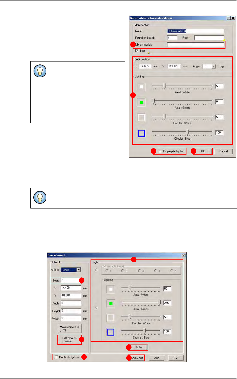
5. Enter the Library model name (A) of the
datamatrix or barcode.
4.7.7 Create Skip or Global Skip
A global skip allows inspecting or not all the sub-panel skips, it is associated to the board number 0.
4.7.7.1 Creation procedure
1. Open a .tst file then load the corresponding panel.
2. In Edit menu select Board then Create a skip to open New element window.
3. The window New element appears after the fiducials inspection.
- You can modify the CAD position
or the lighting (
B).
- You can propagate the lighting by
picking the option (
C).
By right clicking, datamatrix \ bar-
code parameters could be propa-
gated or deleted.
These adjustments must be saved
by clicking on
OK button.
- If a global skip is found the sub-panel skips will not be executed.
- If a global skip is not found all the sub-panel skips will be executed.
A
B
C D
F
A
B
C
D
E
New element creation
.TST file creation
Vision 2007 4.10 User Manual Rev 01 4 - 25
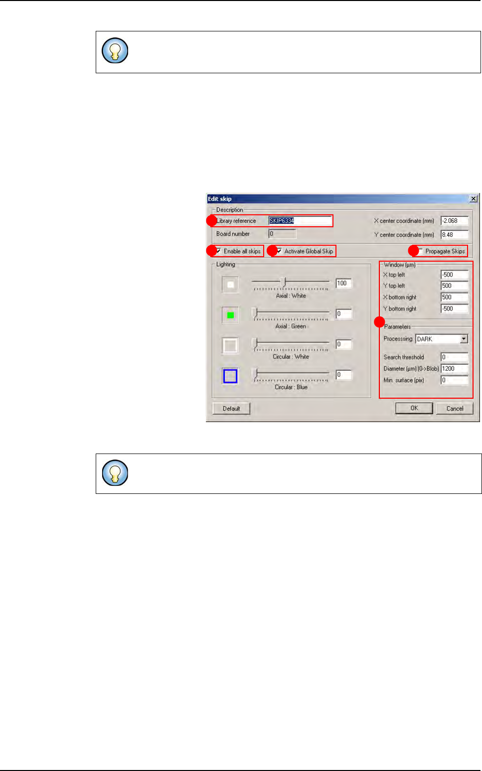
4. Define the lighting level (A), take a photo if needed by clicking on Photo button (B).
5. Put the board number, in the board field (F). 0 to create global skip or the sub-panel
number to create a normal skip.
6. Define the position of the skip by clicking on the .tst file then adjust the skip location
with the Edit area on console button (C).
7. You can duplicate the skip creation by board by picking the option Duplicate by board
(D).
8. Click on Add & edit
button, the Edit Skip
window is displayed.
9. Enter the library ref-
erence, if the skip use a
library model (A).
10. Tick the option En-
able all skips to acti-
vate all normals skips
(B).
11. Tick the option Ac-
tivate Global skip to
activate global skip (C).
12. The skip parame-
ters could be propagat-
ed to all skip by picking
the option Propagate
skips (D).
13. Adjust the window and the parameters for the skip search (E).
If fiducials are not correctly acquired a shorter version of the New element
window is displayed.
These adjustments must be saved by clicking on OK button.
A
B C D
E
New element creation
.TST file creation
4 - 26 Vision 2007 4.10 User Manual Rev 01
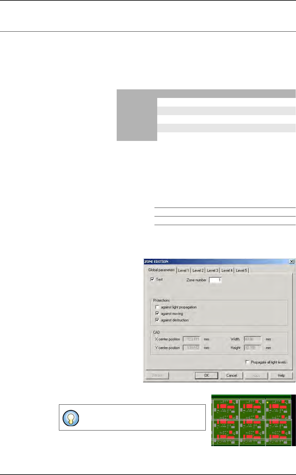
4.8 Zones creation
4.8.1 Zones presentation
Zones can be created automatically by the menu or via the creation of the .tst file or manually.
Zones will be created with defaults values that are defined in Default.ini file. Each zone can have
its own properties and its own light levels. A zone can be created on any components even if it
is not executable (to create zones on only executable ones a flag must be set in the menu).
Zones are associated and
regrouped into zones layers
displayed in a small window
when the Display zones
menu is selected. Zones
may have different colors
as shown opposite.
4.8.2 Zones.dsc file and default values
Zones.dsc file is a structured file. The file memorizes the characteristics of the joker zones like
Jedec codification, centering property, light level settings, same for the centered zones (Jedecs).
This file will be used and shared by all the tst files. Zones.dsc file content is displayed during the
automatic zones creation for centered and Joker zones.
Default values are kept in the Default.ini
file that can be acceeded by the user.
4.8.3 Type of zone
4.8.3.1 Standard zones
Standard zones can be created
on all the components except
very large ones that need multi-
zones. The user can check the
box
Propagate all light levels
if
he had modified light levels set-
tings. It will copy the 5 light levels
settings on all the standard zones
and multi-zones which are not
protected against
Light propa-
gation
. The
Default
button will
removed the light levels settings
modifications and set the default
ones that are defined in
De-
fault.ini
file.
Standard zones are defined by a continuous mauve line.
4.8.3.2 Multi-zones
By default, a standard zone is created without
any protections.
Standard/Centered Multi-zones Joker
In test purple white blue
Not in test Red Red Red
Protected dotted line dotted line dotted line
Not protected continuous line continuous line continuous line
Selected yellow yellow yellow
ZONE JOKER CENTERED ON JEDEC TRUE (value 1)
ZONE FILE PATH C:/VIT/CONFIG/