VI User Manual.pdf - 第109页
Vision 2007 4.10 User Manua l Rev 01 5 - 1 Chapter 5 .TST file edition 5.1 .TST file transformation and polarity 5.1.1 . TST file rotation Once the .t st file has been create d, y ou can ma ke your te st file r otate , i…
.TST file creation
4 - 34 Vision 2007 4.10 User Manual Rev 01
Case 5: the component is not defined in the zone file or the zone file is empty. The zone
edition window is displayed. Adjust the light settings.
Click on OK to validate your settings, the zones file
is updated with the new Jedec name and its re-
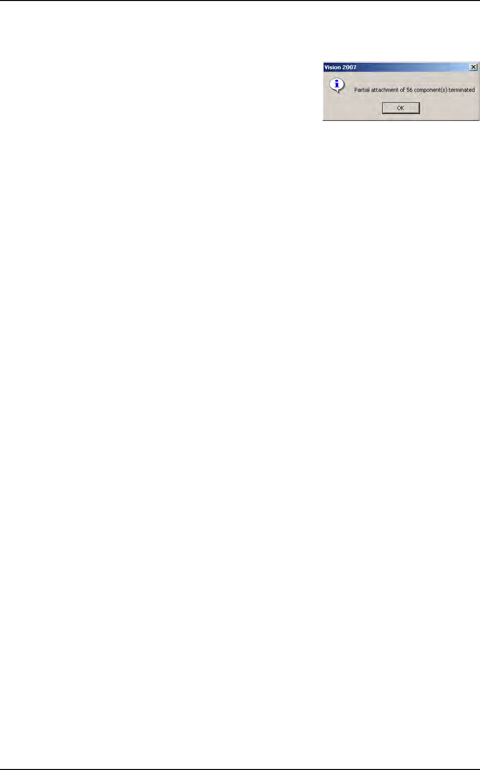
quired light adjustments. An information message
will appear confirming the re-attachement of the
components.
Second step if needed
Propagate these settings to the other components of the same Jedec.
1. Go to the pulldown menu Edit\Board\Create Joker zones to open a dialog box that
displays the content of the zone.dsc file. It then show the list of all jedec which have
already been configured with a joker zone.
2. Check the corresponding check boxes for the jedec you want to add joker zones.
Zones creation
Vision 2007 4.10 User Manual Rev 01 5 - 1
Chapter 5
.TST file edition
5.1 .TST file transformation and polarity
5.1.1 . TST file rotation
Once the .tst file has been created, you can make your test file rotate, in Edit menu go to Trans-
formation, choose Rotation sub menu and select 90°, 180° or 270°. The test file will be rotated
and all zones will be re-created.
5.1.2 Automatic Rotation of programs for Vi-1K with camera at 90°
This option allows to rotate automatically test file on Vi-1K with a camera at 90° to insure the
compatibility between offline and online programs.
It is mainly used when a test file is modified on offline machine (Vi-1K with a camera at 90°) and
used for panel inspection on online machine. After this rotation, zones are not recreated and
lighting levels are kept.
This option is available from the defaultValue.ini file by activating the key Temporarily rotation
angle (deg) = 270 in the [Test File] section.
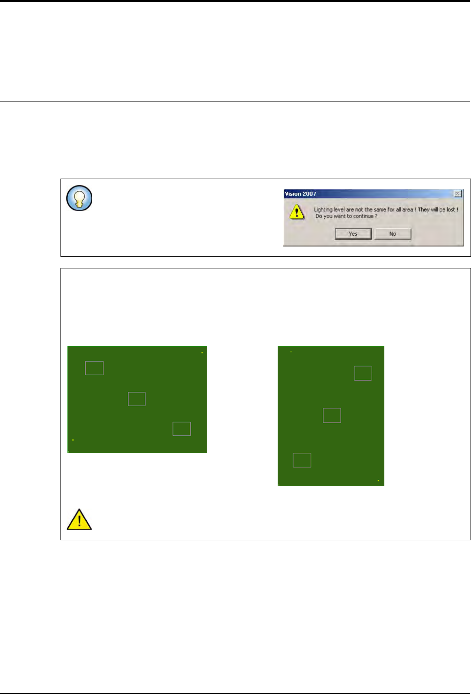
If you have different settings, you have the
opposite message.
.TST file rotation without modification of zones position
To avoid zones re-creation, the user can activate the option rotation of zone before the test
file rotation.
It is mainly used to exchange test files between a Vi-1K with a camera at 90° and a Vi-3K with
a camera at 0°.
After this rotation, the test file can not be executed on the machine type where
the rotation takes place.
.TST file before rotation
.TST file after rotation by 90°
.TST file edition
5 - 2 Vision 2007 4.10 User Manual Rev 01
5.1.3 Mirror transformation
In Transformation menu, you can choose also mirror to rotate the .tst file with an horizontal or
vertical axis.
5.1.4 Change orientation
From the menu Edit / Transformation / Change orientation, the user can define the conveyor
flow direction used (Right Left or Left Right).
5.1.5 Global offset
This functionality allows applying a defined offset value on fiducials only, on components, text
and trace objects, or on all of them.
This offset can be applied to the whole panel or to one particular board.
The Global offset window is available from menu Edit /
Transformation / Global offset.
5.1.6 Polarity display
To see the components polarity mark on the repair station, configure them in the .tst file. 2 types
of polarity marks can be imported:
in a corner or on one side of the component
Indicate the position of the polarity for each Part Number, in a text file and import it in the .tst file.
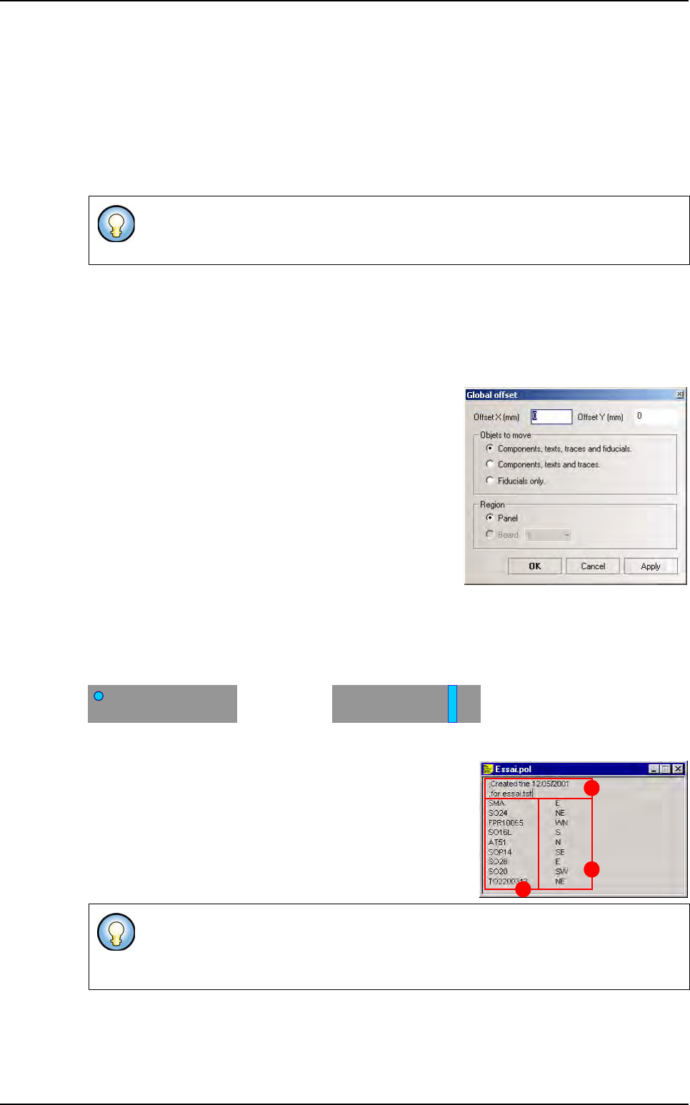
To import a .tst file, create a text file, with any name but with
the extension .pol, that contains:
A The comment lines begin by ; (only for .pol files)
B Part_Number
C Its polarity location
Open your .tst file and in the menu Test file go to Import sub menu and select Polarity file. You
will see the polarity marks on the components. If you select no file, you will lose the previous po-
larity marks. If your .pol file has syntactic errors, a .log file will be created containing the error
message.
On a right to left machine: the reference is the bottom left hand corner of the board.
On a left to right machine: the reference is the bottom right hand corner of the board.
To indicate the polarity location, use: N for North, S for South, E for East, W for West.
Using 1 letter will generate a linear polarity and a combination of 2 letters will generate
a circular polarity in a corner.
A
B
C
.TST file transformation