VI User Manual.pdf - 第41页
Maintenance mode Vision 2007 4.10 User Manua l Rev 01 2 - 5 2.1.2 Focus The Focus function allows optimu m adjustment of the camera focus and ensures homogeneity between machines. Optimum focu s is obtained when the abso…
Maintenance mode
2 - 4 Vision 2007 4.10 User Manual Rev 01
4. Manually adjust the lens opening (top ring) of the camera and click Start test to obtain
the new value of measurement for each lighting.
5. Repeat this operation until the value of gray level measured is equal (+/- 10) to the
reference value (120) for the weakest lighting (Values out of range are underlined in
red). Then the Auto Calibration button is activated.
6. Click Auto Calibration. Auto calibration of gray levels begins: this procedure may take
more than 2 minutes.
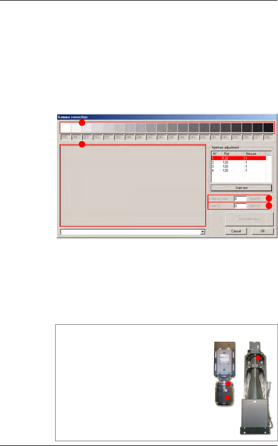
2.1.1.3 Calibration results
Once the calibration is over, the Gamma correction window displays the calibration
values and graphs:
The gray scale (A) displays, for each shade of gray, the measured values, used for gam-
ma correction.
Delta GL max (B) indicates the maximum difference in gray levels between the theoret-
ical gamma values and the corrected values. This value should be less than 8 gray levels
if the gamma correction is successful.
Used GL (C) indicates the number of distinct gray levels available when the gamma cal-
ibration is active. This value should be at least 225 (which is the number of distinct gray
levels available without gamma correction).
The different graphs (D) represent the measured and computed values at different stag-
es of the calibration process.
Cameras
The Vi-3K Series and Vi-5000 Series camera lens is accessible
from the rear of the machine.
A Top: lens opening ring.
B Bottom: focus ring.
A
D
B
C
A
B
A
Test machine
Maintenance mode
Vision 2007 4.10 User Manual Rev 01 2 - 5
2.1.2 Focus
The Focus function allows optimum adjustment of the camera focus and ensures homogeneity
between machines. Optimum focus is obtained when the absolute value of the test is at its high-
est.
1. Click on the Focus button for automatic adjustment of conveyor width.
2. Insert the calibration tool in the machine, then adjust focus.
3. Once you have activated the test, adjust focus: the blue bar-
graph increases or decreases according to the Absolute val-
ue marked below:
32 µm camera: take up or down the focus ring (bottom ring
on the lens) until Absolute value reaches its maximum val-
ue.
26 µm camera: take up or down the camera (remove the
beamsplitter cover and loosen the 3 camera flanges) until
Absolute value reaches its maximum value.
4. Click Stop test & Exit when the operation is complete.
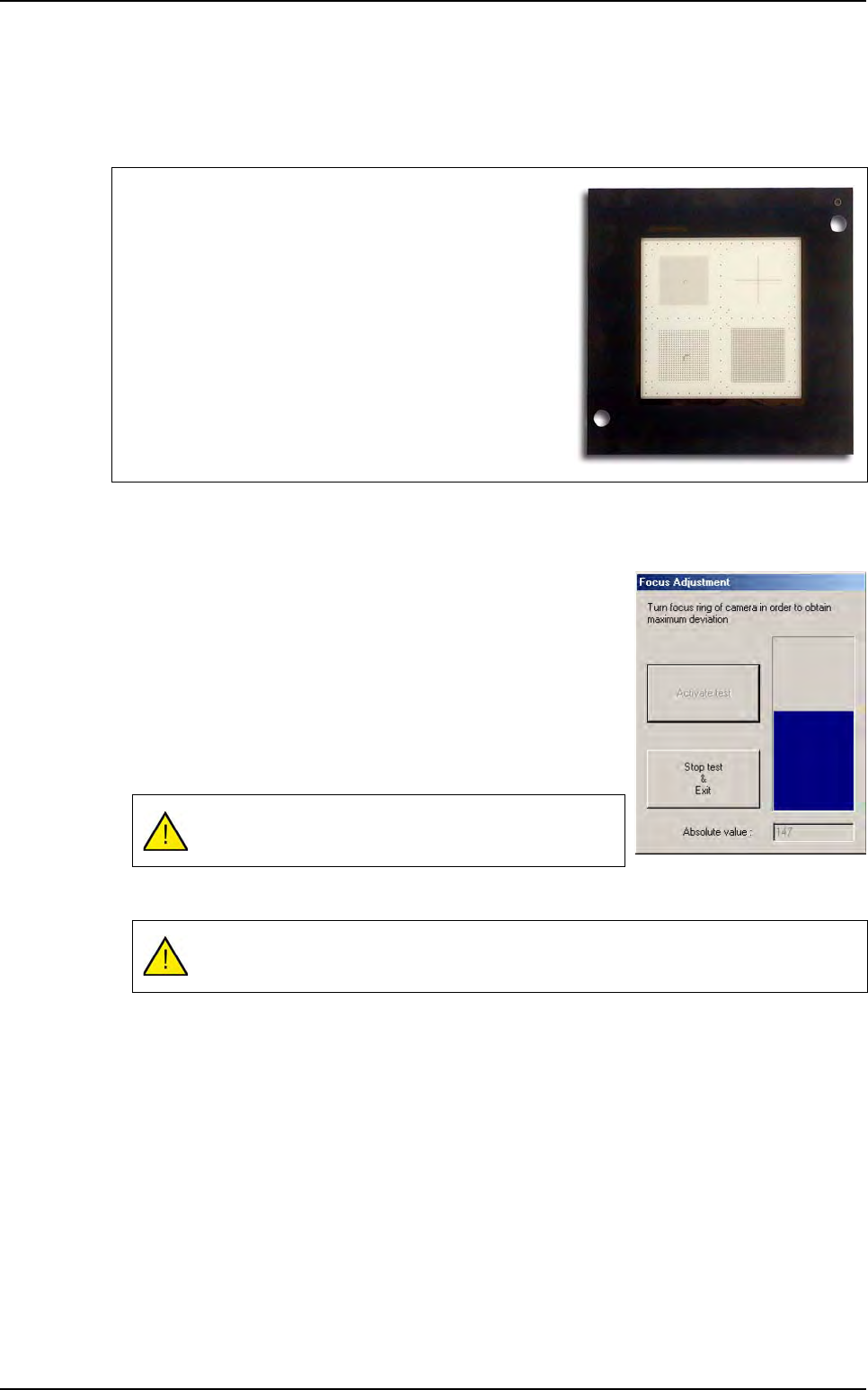
Focus is adjusted using the calibration tool supplied with the
machine.
Make a visual control of the calibration tool frequently, in or-
der to check that it is not scratched.
The Absolute value must be to the maximum.
This operation must be repeated each time the camera is modified.
Test machine
Maintenance mode
2 - 6 Vision 2007 4.10 User Manual Rev 01
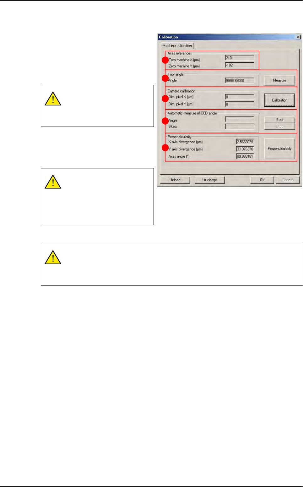
2.1.3 Calibration
Once you have adjusted camera focus
and lens opening, you can calibrate the
machine using the glass calibration tool .
The Axes references (A) are the dis-
tances between the axis 0 (middle of the
axis) and the machine 0 (panel stop).
The Tool Angle (B) must be 0° to per-
form the calibration. Measure lets you
calculate the angle of the calibration tool
with respect to the axes.
The Camera calibration (C) measures the pixel size.
In Automatic measure of CCD angle (D) section, press Start to measure the angle of the CCD
with respect to the axes.
Perpendicularity (E) of axes and deviation.
Click OK to confirm the values entered by default or the changes made.
2.1.4 Auto check
The Auto check is a function used to verify proper operation of the optical and mechanical parts
of the machine by means of a glass plate calibration tool:
Pixel size,
Axes angle,
Axes pitch,
Machine accuracy,
Machine repeatability.
If you change the position of the
stop, these values must be
changed in the parameters
menu.
The tool angle must be zero to
perform the following measure-
ment.
The calibration tool must be
parallel to the axis (tool angle:
+/- 0.005°).
If the pixel size is too large, lower the camera.
If the pixel size is too small, raise the camera.
Any vertical movement of the camera will require adjustment of focus.
A
B
C
D
E
Test machine