VI User Manual.pdf - 第339页
Optimization Vision 2007 4.10 User Manua l Rev 01 12 - 21 12.4 Profiler ™ Automatic Setting 12.4.1 Presentation The Profiler ™ Automatic Setting allows to automatically set each Profiler ™ you have cre- ate (just for Pro…
Optimization
12 - 20 Vision 2007 4.10 User Manual Rev 01
12.3.6.4 More details
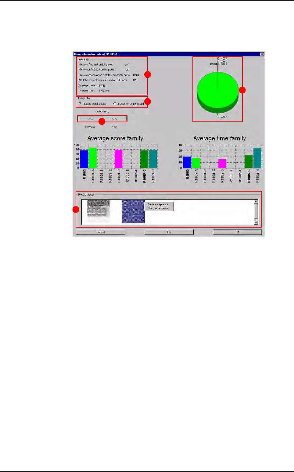
By double clicking on a model from the Customer or Standard library, the window
below appears.
In
Information (A) section:
Nb pass/nb test on full panel: number of times this link has found the compo-
nent (sufficient score).
Nb winner/nb test on full panel: number of times this link gave the best score.
Nb false acceptance/nb test on empty panel: number of times the model gave
false acceptances on empty panel.
Nb false acceptance/nb test on full panel: number of times the model gave
false acceptances on full panel.
Average score: sum of the scores divided by the number of times components
passed with this link.
Average time: sum of the inspection times divided by the number of times the
link wons.
In
Image filter (B) section, select the images from empty or full board. For models
from the standard library, you can see pictures on the detail screen. These pictures
are taken when a standard model validates a component.
Press
<<<< or >>>> (C) button to see the next or previous links.
The pie chart (
D) shows you the links distribution for one family of components ac-
cording to the winner %.
In
Picture viewer (E) section, use the right click on images to agree the inspection
result or to change statistics if it corresponds to a false acceptance:
Good acceptance
: the vision result is good. You will delete this image from your disk,
False acceptance: the vision result is wrong. You will change statistics and de-
lete the image.
A
C
D
E
B
Auto Defect Correction (ADC)
Optimization
Vision 2007 4.10 User Manual Rev 01 12 - 21
12.4 Profiler
™
Automatic Setting
12.4.1 Presentation
The Profiler™ Automatic Setting allows to automatically set each Profiler™ you have cre-
ate (just for
Profiler™ in Custom tool). To automatically set the Profiler™ you need several
good boards. You need to be sure that there are no defect on these boards (for the model
you want to set). During the automatic setting, all profiles of components are collected, and
tolerances are automatically constructed around them. Tolerances are calculated by statis-
tic, so more boards you use, more tolerances are accuracy. A wizard is available to help you
to select model you want to set.
Before launching automatic setting you need to:
Define the Profiler™ (define the size, position, lighting)
Create the reference
If you use the Peak threshold algorithm, define the threshold and limits (to ignore some
parts).
If you use the 3D analysis algorithm define the limits (to ignore some parts).
If you use an algorithm (other than tolerances) choose the operator of the difference to
average
algorithm (Lead to lead algorithm)
Propagate these parameters to all leads
12.4.2 Profiler Automatic Setting wizard
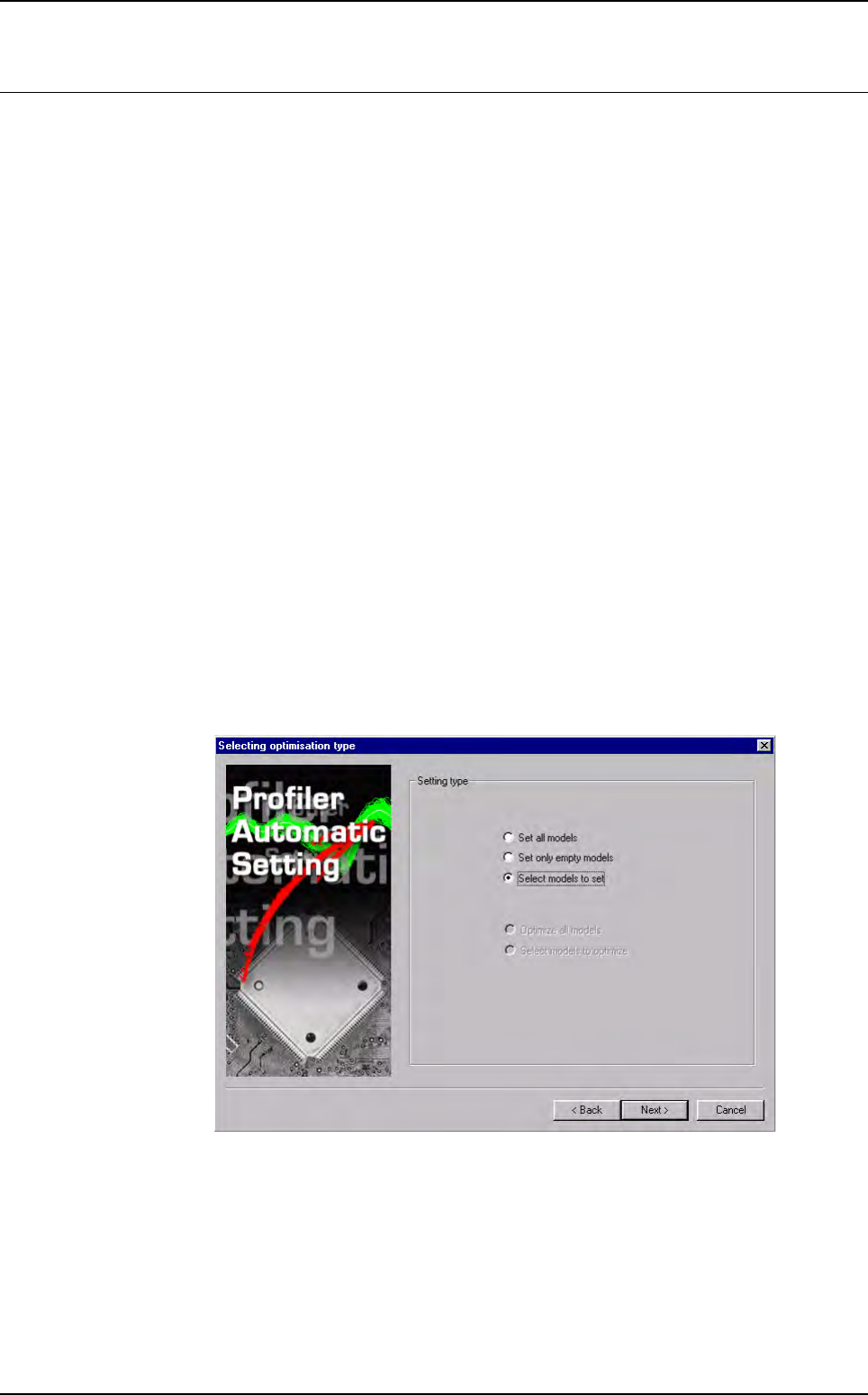
12.4.2.1 Selecting optimisation type
By default Select models to set is ticked to choose models Profiler™ to set.
Tick Set all models to set all models Profiler™ (programmed and unpro-
grammed).
Tick Set only empty models to set all models which Profiler™ are never pro-
grammed.
Click on
Next > button.
Optimization
12 - 22 Vision 2007 4.10 User Manual Rev 01
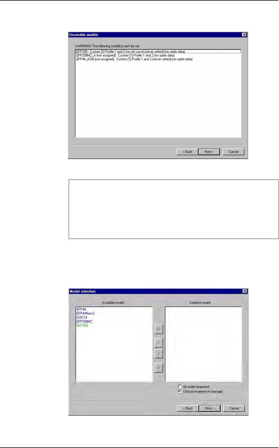
12.4.2.2 Unsetable models
In the window above, the unstable models list appears with the reasons showed be-
tween brackets.
Click on
Next > button.
12.4.2.3 Model selection
Choose the model to autoset.
Use
>, >> and <, << buttons to select or unselect model to set.
Model you can set:
Model who contain 1 or several custom
Custom must have the 2 Profiler™ programmed
Profiler™ must have a reference curve
Each Profiler™ must be uniform (propagate setting to all leads)
Profiler
™
Automatic Setting