VI User Manual.pdf - 第171页
Tools library Vision 2007 4.10 User Manua l Rev 01 7 - 9 7.2 Model edition With the library opened, doub le click on the model that you want to edit, to disp lay the Edit a model window. 1. Select the image of the compon…
Tools library
7 - 8 Vision 2007 4.10 User Manual Rev 01
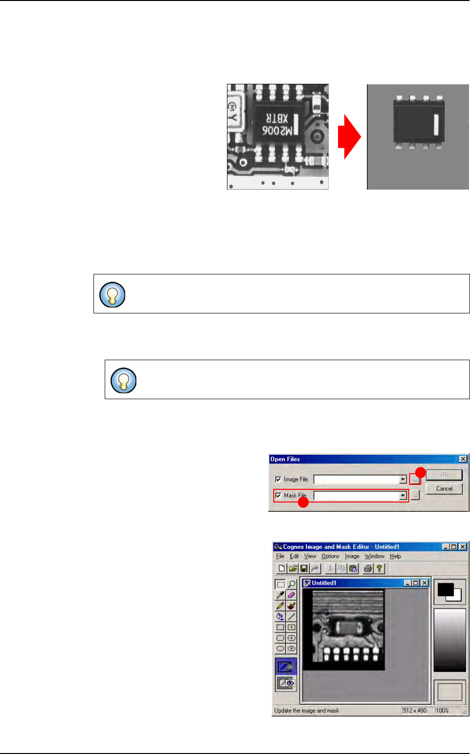
7.1.4 Creating synthetic models with Image Edit
7.1.4.1 Image Edit description
Images created by
Image Edit
are real images from the Full
board library, but modified to
extract, highlight or enhance
their features.
This allows to emphasise
what the inspection tools
should look for, and ignore
features that are not or less
important. This also results in
increased inspection perfor-
mance.
Select a representative pattern with consistent features. Reduce needless features and
image noise. Train only important features. Consider editing bitmaps to create a repre-
sentative pattern. Larger patterns will provide greater accuracy. High frequency features
are more significant at outer edges of patterns.
7.1.4.2 Image Edit using
1. Select ImgEdit in the Edit menu.
2. The Cognex Image and Mask Editor window appears (see below). A tool box to mod-
ify the image is presented: enhance the lines that you want to keep for the inspection,
or delete those that seem to be unimportant.
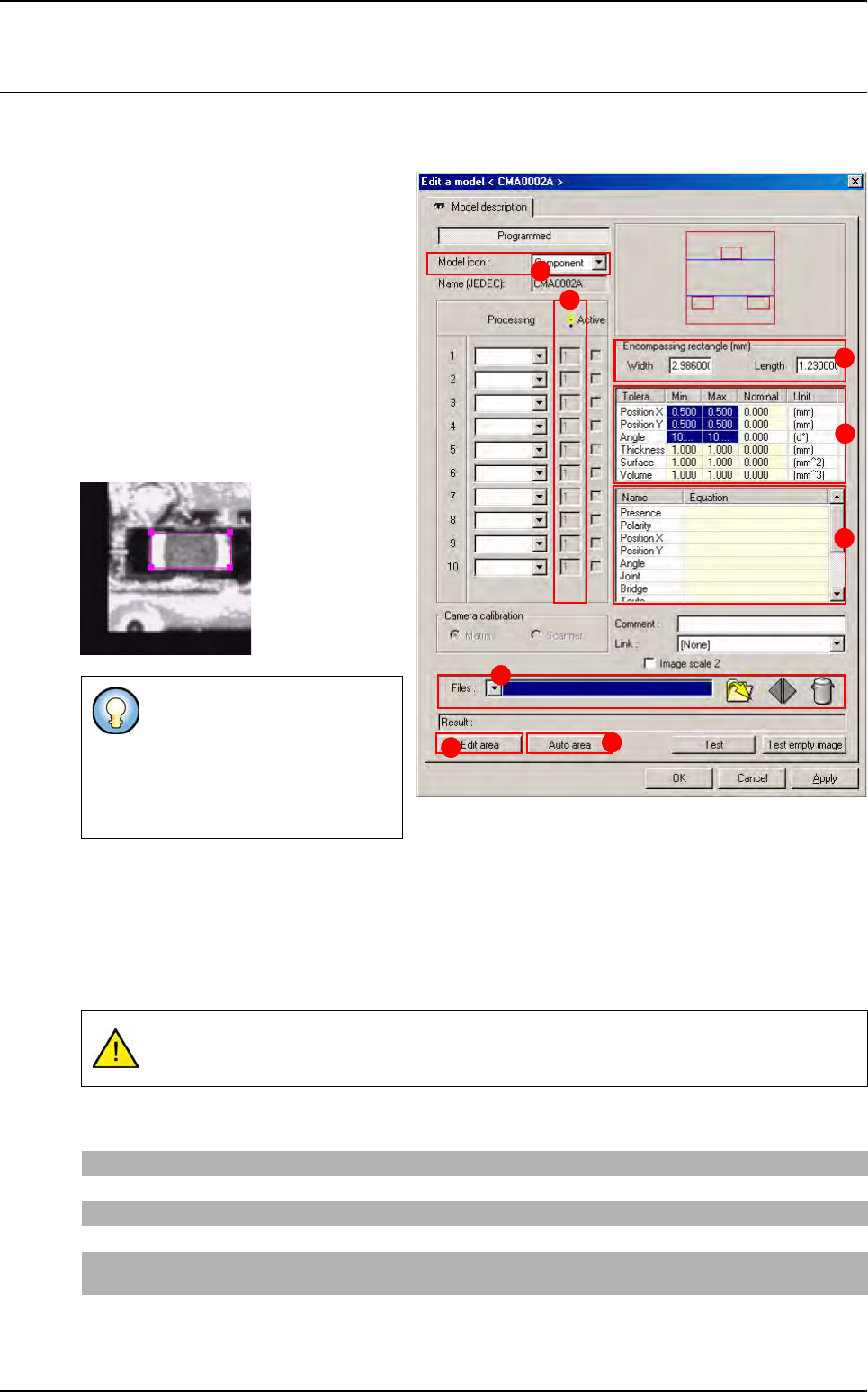
3. To display a component image, go
into the File menu and click Open
(Ctrl+O). The Open Files window
appears. Click this button (A) to
choose the real image of the model
that you want to modify and remove
the tick from Mask file (B).
4. The Image Edit window is activated,
with the selected image (lighting lev-
el) of the model.
5. Click on the Save icon in the tool bar
to save the modified image of the
model or select Save (Ctrl+S) in the
File menu then Exit in the same
menu to return to Vision 2007 main
screen.
6. Select Create model from current
series from the Models menu to en-
able the newly modified image to be
listed in the component library.
Image Edit is used to convert real images into synthetic images.
A library must be opened to access the Edit menu.
Original real image
Lines that are not important
to the inspection are deleted.
Synthetic image from Image Edit
A
B
Component library
Tools library
Vision 2007 4.10 User Manual Rev 01 7 - 9
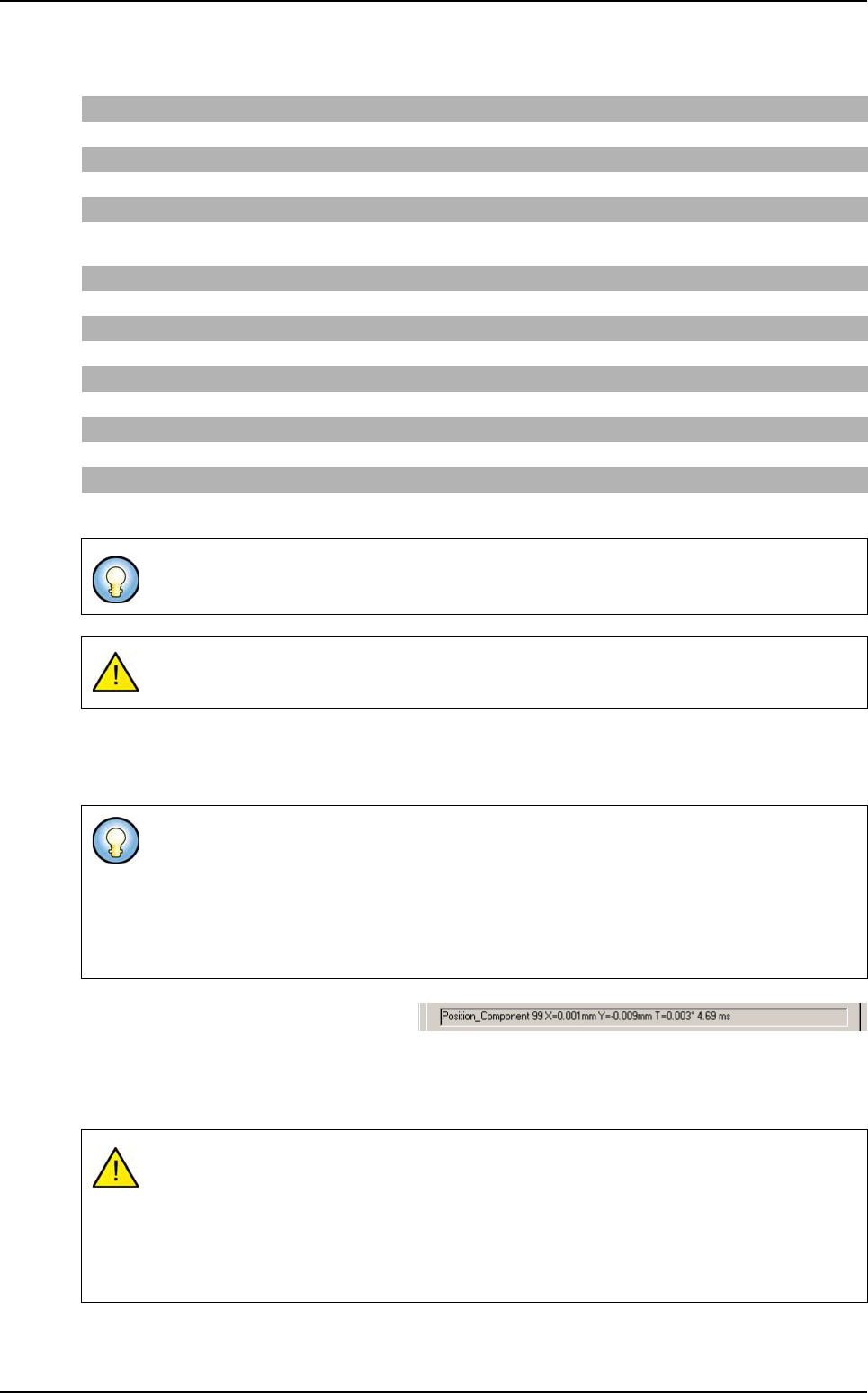
7.2 Model edition
With the library opened, double click on the model that you want to edit, to display the Edit a model
window.
1. Select the image of the component that
you want to program from the list avail-
able in Model image (A) to display the
selected image or browse the image with
this button.
2. Select in Model icon (B), the icon repre-
senting the type of component being
treated.
3. When you click on Edit the area (C) but-
ton a magenta contour appears in the
camera window. Drag and resize this
contour and outline the model image cor-
rectly.
Deactivate the Edit area function by clicking it again. The characteristics of the Encompassing rect-
angle are automatically filled in during step 3.
The Auto area (E) button enables positioning of the encompassing rectangle. The automatic area
edition can be performed if, and only if, the model used is a synthetic model.
4.
In
Tolerances (mm)
(
F
) section,
enter the inspection tolerances ( X, Y and Theta) for the current model.
5. In Equations (G) section, enter the equations to be used for component test.
This magenta rectangle called the
Encompassing
rectangle
(
D
) is
used to define the size of the com-
ponent in the library and therefore
in the associated .tst file during its
creation.
If the tolerances are zero, the inspection result will always be a position error (the perfect
position does not exist).
Presence
Enter the processing window number. If this is the window 1, part R1 (R for Result).
Polarity
Enter the window number in the different text fields if a component requires one of the tests mentioned.
Position X and Y
Enter X1 or Y1 to have the position of the tool in window 1.
Angle
Enter T1 in the Angle text field to indicate that the angle is calculated by the inspection tool of window 1.
Joint
Enter the processing window number. If this is the window 1, part 1-J1 (J for Joint), only if you have a SO
or QFP tool in the window 1.
Bridge
Enter the processing window number. If this is the window 1, part 1-B1 (B for Bridge), only if you have a
SO or QFP tool in the window 1
A
B
C
E
F
G
D
H
Tools library
7 - 10 Vision 2007 4.10 User Manual Rev 01
Here is the list of the available formulas that you can use in the equation fields
6.
Select the light level (
H
) for this treatment. Now that the model description is complete, the different
treatment windows must be determined using the different inspection tools: Vi-Pro, Edge, Histogram,
SO, QFP, Custom, BGA.
7. Component test according to the equa-
tions entered in the model description. Af-
ter returning to the Model description tab, click on Test button. This test will apply all the tools from
the active windows. Examine the inspection results and make any modifications necessary.
8. Click OK to validate the parameters and close the window.
Logical operator
OR, AND, NOT, <, >, == , <=, >=, Test?Res1:Res2
Numerical operator
=, +, -, *, /, -NEG, X^i
Functions
SIN, COS, TAN, ATAN, LN, LOG, EXP, SQRT, ABS, MOD 180 (to ensure angle between 0 and 180°), MODPI (to ensure
angle between 0 and Pi), D2R (convert Degree to Radian), R2D (convert Radian to Degree)
Vi-Pro variables
Ri, Xi, Yi, Ti, Si (Fit error), Ui (scale X), Vi (scale Y)
SO / QFP variables
Ri, Xi, Yi, Ti, Ji (joint), Bi (bridge)
Edge
Ri, Xi, Yi, Ti, Wi (width), Oi (offset), Ci (contrast)
Histogram
Ri
Custom
Mi (maximum histogram for joint inspection), Zi (number of leads with profil error)
If you need the CAD data in an equation, you can use the following variables: X0, Y0 and
T0.
When closing model, if there is no equation in the parser, you have a warning message.
If you right click on the treatment number, a menu box appears with the option to copy or
cut a treatment. You can copy a treatment and paste it in another model only if both are 2
mono zones models or 2 multi zones models. You can paste it on another window. All the
treatment parameters will be paste.
If you paste a treatment on an existing one, you have a message box asking you if you want
to overwrite the existing treatment.
Advice for the model edition:
Save the library (re-synchronization with the .tst file is automatic).
Save the .tst file.
Perform the test on the panel and therefore on the different components to ensure that the
treatment operation is properly applied.
Model edition