VI User Manual.pdf - 第354页
Reparation 14 - 2 Vi sion 2007 4.10 User Manual Rev 01 We can use the repair station in on-line or off-lin e configuration. The on-line and off-line re pair sta- tions are operated in almost th e same m anner. The major …
Vision 2007 4.10 User Manual Rev 01 14 - 1
Chapter 14
Reparation
14.1 Overview
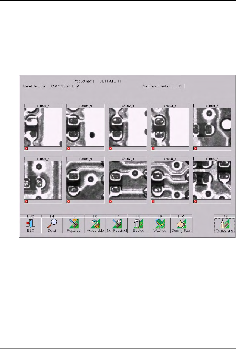
The repair station is where the inspection faults from the AOI systems are reported and attended to.
From the repair station you can:
View the CAD representation of the board.
Display the exact position of the fault to be repaired on the board.
View the actual photo of the fault as taken by the AOI system.
Decide to repair, accept, ignore or notify of a false fault.

Reparation
14 - 2 Vision 2007 4.10 User Manual Rev 01
We can use the repair station in on-line or off-line configuration. The on-line and off-line repair sta-
tions are operated in almost the same manner. The major differences are as follows.
14.1.1 On-line
Faults reported by the AOI system are stored in the supervisor database and automatically
forwarded to the repair station after the board has left the AOI system. Both machines are
linked by a SMEMA connection. Boards repaired on the on-line repair station are immediate-
ly released back to the production line.
14.1.2 Off-line
Faults reported by the vision system are stored in the supervisor database and only forward-
ed and displayed on the repair station upon request. The operator requests board informa-
tion by means of a scanner to read the bar code information or by using the keyboard.
14.1.3 Off-line FIFO (First In First Out)
After selecting the product to repair, the software display automatically the first board to re-
pair. This mode is useful to repair boards without code identity. The off-line repair station, or
off-line rework allows buffering of faulty boards to be attended to in non-real time.
Overview
Reparation
Vision 2007 4.10 User Manual Rev 01 14 - 3
14.2 Reparation launching
14.2.1 First launching
The first time, the Reparation software is launched, a wizard is executed. It presents the fol-
lowing windows.
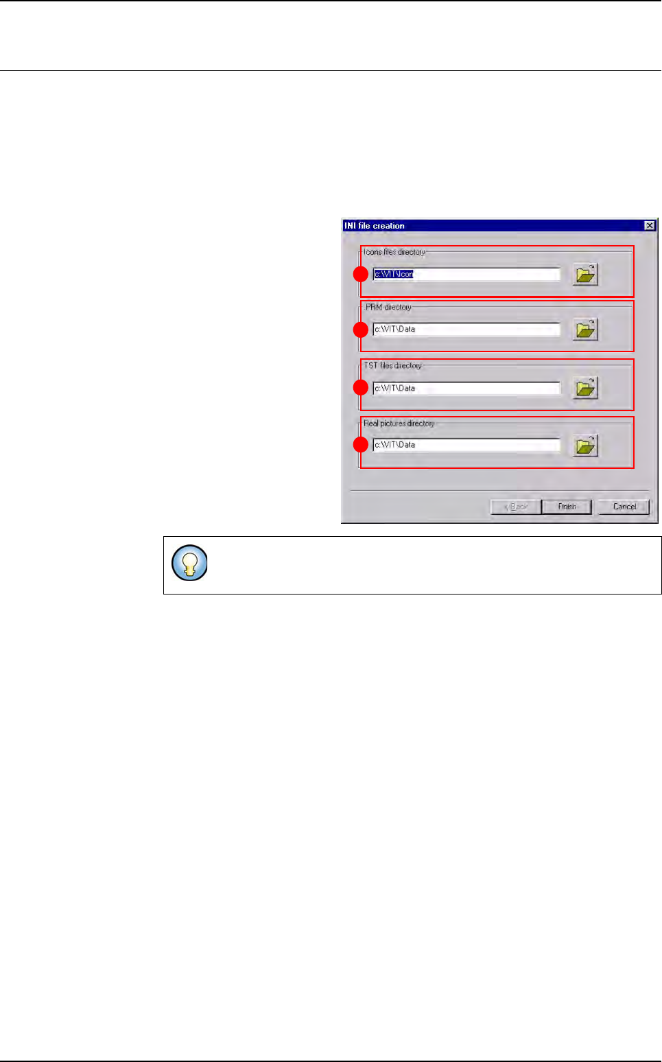
14.2.1.1 Path Setting window
This window lets you choose:
The Icons files directory
(A) where the software will
find the icons of each but-
ton.
The .PRM directory (B)
where the repair station
configuration file will be
saved.
The TST files directory (C)
where the software will find
the inspection program file.
The Real pictures directo-
ry (D) where the software
will find the images taken by
the AOI system, which show
the defects.
14.2.1.2 Main and detail buttons windows
These windows lets you configure the user interface and functionality of the 1st in-
terface showing the defects to repair. Clicking on one of the button from this inter-
face will set the same values to all the defects. To access to the detail of each defect
press F4 or the associated button.
The button list is totally configurable. You can:
Add and remove some buttons,
Change the text on the button,
Change the symbol on the button,
Change the function associated to the button,
Change the result information saved in the database.
To retrieve this window, go in Configuration menu and select Path set-
ting.
B
C
D
A