VI User Manual.pdf - 第94页
.TST file creation 4 - 20 Vision 2007 4.10 User Manual Re v 01 4.7.2 Create a pad / a reference pad 1. Open a .tst file then load the corr esponding panel. 2. In Edit menu, sele ct Pad , then Add a pad to open New elemen…
.TST file creation
Vision 2007 4.10 User Manual Rev 01 4 - 19
4.7 New element creation
Once the .tst file is created, new elements can still be added: components, pad, connector, text, trace,
datamatrix or barcode, skip and zones.
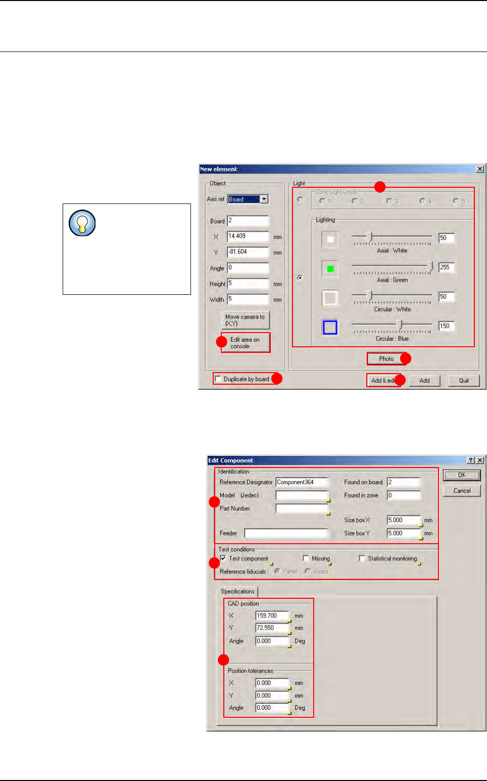
4.7.1 Create a component
1. Open a .tst file then load the corresponding panel.
2. In Edit menu select Component, then Add a Component to open New element window.
3. The window New element
appears after the fiducials in-
spection.
4. Define the lighting level
(A), take a photo if needed
by clicking on Photo button
(B).
5. Define the position of the
component by clicking on the
.tst file, then adjust the com-
ponent location with the Edit area on console button (C).
6.
You can duplicate the component creation by board by picking the option
Duplicate by board
(
D
).
7. Click on Add & edit button (E): the Edit Component window is displayed.
8. The Identification parame-
ters can be set on the A part.
9. The Test conditions can be
selected in the B part.
10. The CAD position param-
eters can be modified in the
Specifications tab (C).
11. The modifications can be
applied by clicking on OK but-
ton, or discarded by clicking on
Cancel button.
If fiducials are not
correctly acquired a
shorter version of
the New element
window is
displayed
.
A
B
C
D
E
A
B
C
.TST file creation
4 - 20 Vision 2007 4.10 User Manual Rev 01
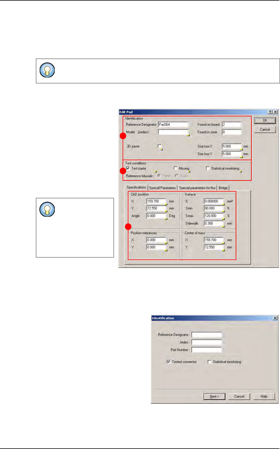
4.7.2 Create a pad / a reference pad
1. Open a .tst file then load the corresponding panel.
2. In Edit menu, select Pad, then Add a pad to open New element window.
3. The window New element appears after the fiducials inspection.
4. Set the parameters as described on chapter 4.7.1, then click on Add & edit button, the con-
figured pad is added on the .tst file, and the Edit Pad window appears.
5. The Identification parame-
ters can be set on the (A) part.
6. The Test conditions can
be selected in the (B) part.
7. The CAD position parame-
ters can be modified in the
Specifications tab (C).
8. The modifications can be
applied by clicking on OK but-
ton, or discarded by clicking on
Cancel button.
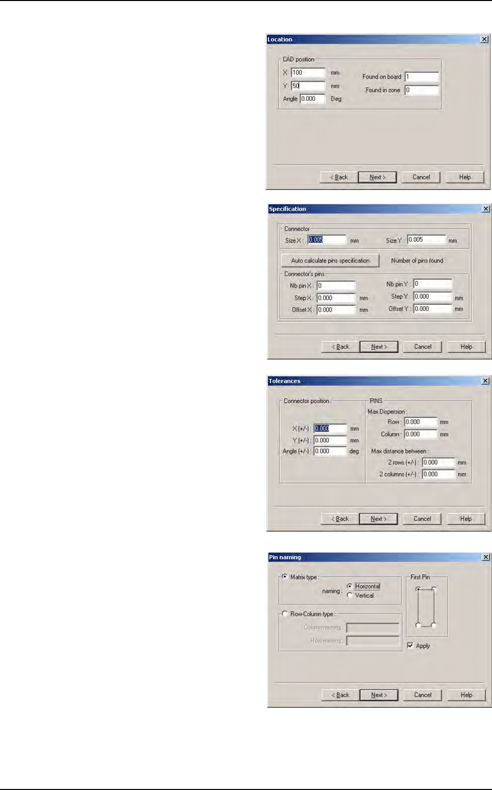
4.7.3 Create a connector
1. Open a .tst file then load the corresponding panel.
2. In Edit menu select Connector then Add a connector to open Identificiation window.
3. The Identification window appears after
the fiducials inspection.
Input the connector identification parame-
ters in Identification window, and then click
on Next button.
If fiducials are not correctly acquired a shorter version of the New element window is
displayed.
Reference pad
menu is only
available for 3D
machines.
3D paste check box
is only available for
3D machines.
A
B
C
New element creation
.TST file creation
Vision 2007 4.10 User Manual Rev 01 4 - 21
4. The Location window appears.
Input the coordinates where the connector
should be created, then click on Next but-
ton.
5. The Specifications window appears.
Input the connector parameters: size and
pins number and position, then click on
Next button.
6. The Tolerances screen appears.
Input the connector and pins positions, then
click on Next button.
7. The Pin naming screen appears.
In the Pin naming window, select the pins
naming rule to apply, then click on Next but-
ton.
New element creation