VI User Manual.pdf - 第68页
.VIS file 3 - 10 Vision 2007 4.10 User Manual Re v 01 Notepad and Wordpad butto ns open the selected text file of the first page. Choose with which software you want to open the text file (Notepad or Wor d pad). Preview …
.VIS file
Vision 2007 4.10 User Manual Rev 01 3 - 9
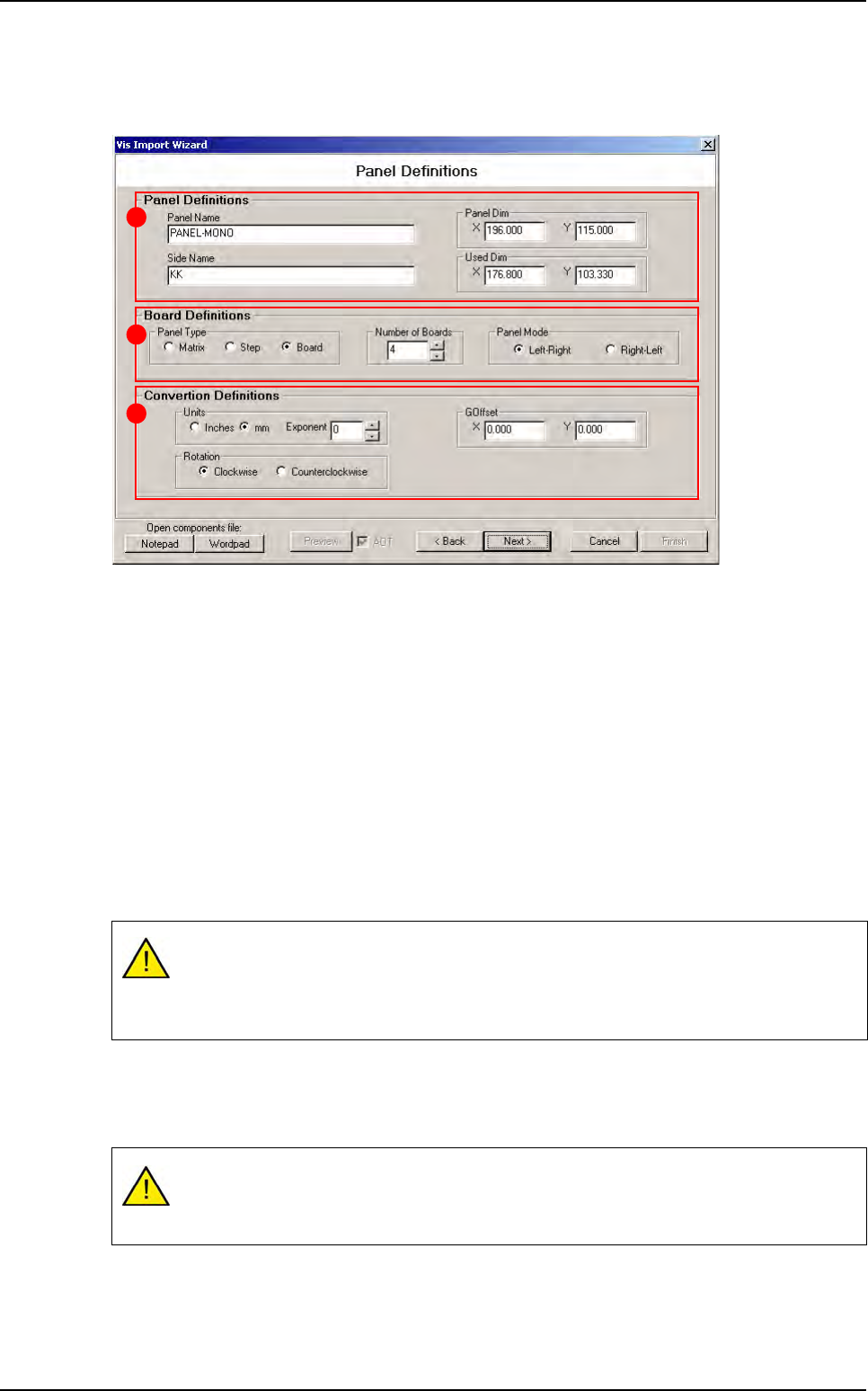
3.2.2 Panel definition window
You have to enter all panel parameters (name, size, number of board, ...).
In Panel Definitions (A) section, define the panel dimension and the used dimension:
The Used Dim is the boundary box of all boards.
The Panel Dim may be bigger than the used dimension.
In Board Definitions (B) section, define:
In Panel Type how the boards are organized in the panel:
- Matrix: all boards are identical and organized as a matrix.
- Step: all boards are identical but their position are not matrix.
- Board: all boards could be different.
The Number of Boards in the panel.
In Panel Mode, the loading way of the AOI system.
In Convertion Definitions (C) section:
In Units part define data unit and exponent.
In Rotation part define the rotation way.
In
GOffset
part, if the component data origin does not match the board origin, apply a global offset.
The machine reference is the stop sensor:
At Right for Left-Right AOI system.
At Left for Right-Left AOI system.
Units and exponent are applied to all values in the wizard. It means that you have to
enter all parameters in the same unit of measurement. You can not enter the panel size
in inch* 10 -2 and component position in mm.
A
B
C
.VIS file wizard
.VIS file
3 - 10 Vision 2007 4.10 User Manual Rev 01
Notepad and Wordpad buttons open the selected text file of the first page. Choose with which
software you want to open the text file (Notepad or Wordpad).
Preview button open a viewer window which display the built panel step by step. At the end of
the wizard, you could see how will be the .tst file created with the .vis file you are building.
So if you tick the AOT (Always On Top) check box, the viewer will stay visible in the foreground.
3.2.3 Board definition window
Enter boards definition (size, position, shape, fiducial position, ...).
There is 3 different types of panel: matrix, step and board.
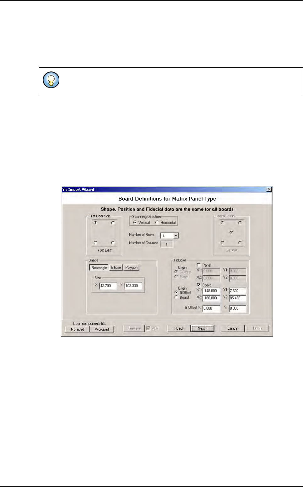
3.2.3.1 Matrix panel type
In Matrix mode, you have to define 1 board shape and the matrix (nb board X nb board
Y), (see paragraph 3.1 .vis file description).
You must define also fiducial position (panel, board or both).
This viewer show you how will be the panel you are building. The mouse right click give
you the opportunity to access to zoom function.
.VIS file wizard
.VIS file
Vision 2007 4.10 User Manual Rev 01 3 - 11
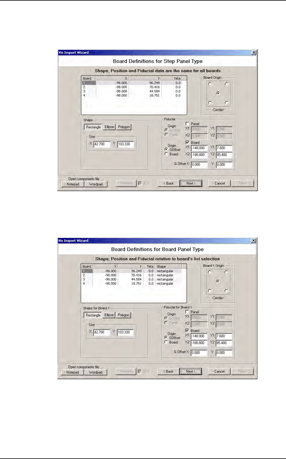
3.2.3.2 Step panel type
In Step mode you have to define 1 board shape and also boards position and orientation
in the panel.
Fiducial position must be defined too.
3.2.3.3 Board panel type
In Board mode, you have to define all board shape separately.
Click on a line in the list to select the board you want define. In this case, shape is a poly-
gon, you can define all apex position.
You must also define fiducial position for all boards if you have board fiducial.
.VIS file wizard