VI User Manual.pdf - 第282页
2D solder paste inspection 9 - 4 Vision 2007 4.10 User Manual Re v 01 9.2 Solder paste in the .tst file 9.2.1 Put pads in test This function enables conside ration of the feeder files that can be imported for the compone…
2D solder paste inspection
Vision 2007 4.10 User Manual Rev 01 9 - 3
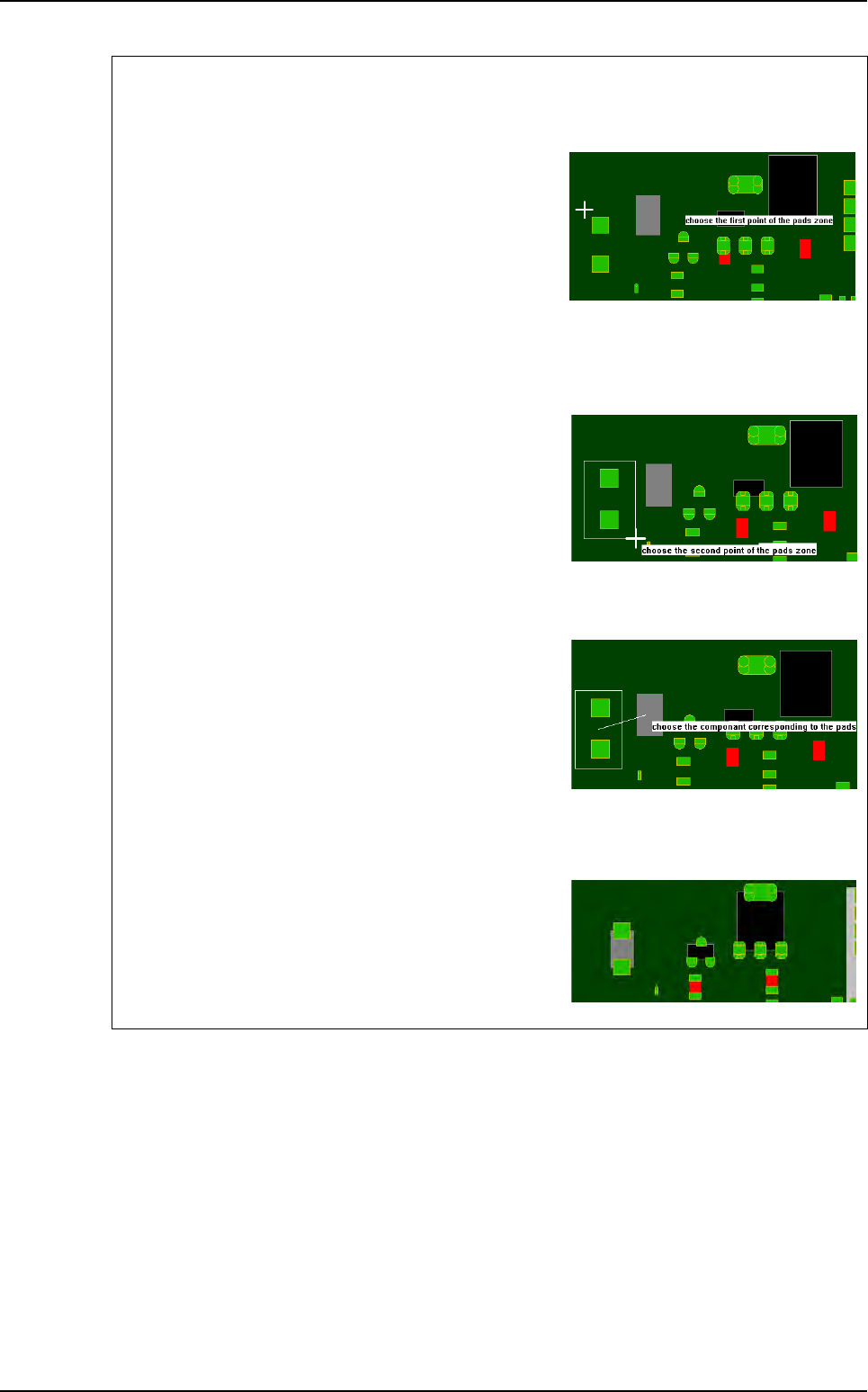
Graphic selection of the pads and the corresponding component
1st step
Click on the 1st point to describe the encompassing
rectangle of the pads group.
To exit the mode:
- During the pads group selection, select an empty rect-
angle.
- During the component selection, click outside of a compo-
nent.
2nd step
Click on the 2nd point to describe the encompassing
rectangle of the pads group.
You must still use offset to set gerber in view.
3rd step
Click on the component corresponding to the pads
group.
During the selection, you still can use the zoom and the
scroll bars.
Result
The software analyses the center of gravity of all the se-
lected pads and moves the gerber mask to make this
point coincide with the center of gravity of the selected
component.
Gerber file
2D solder paste inspection
9 - 4 Vision 2007 4.10 User Manual Rev 01
9.2 Solder paste in the .tst file
9.2.1 Put pads in test
This function enables consideration of the feeder files that can be
imported for the components.
If a component is excluded from the test, its paste pads can be sent
for testing automatically.
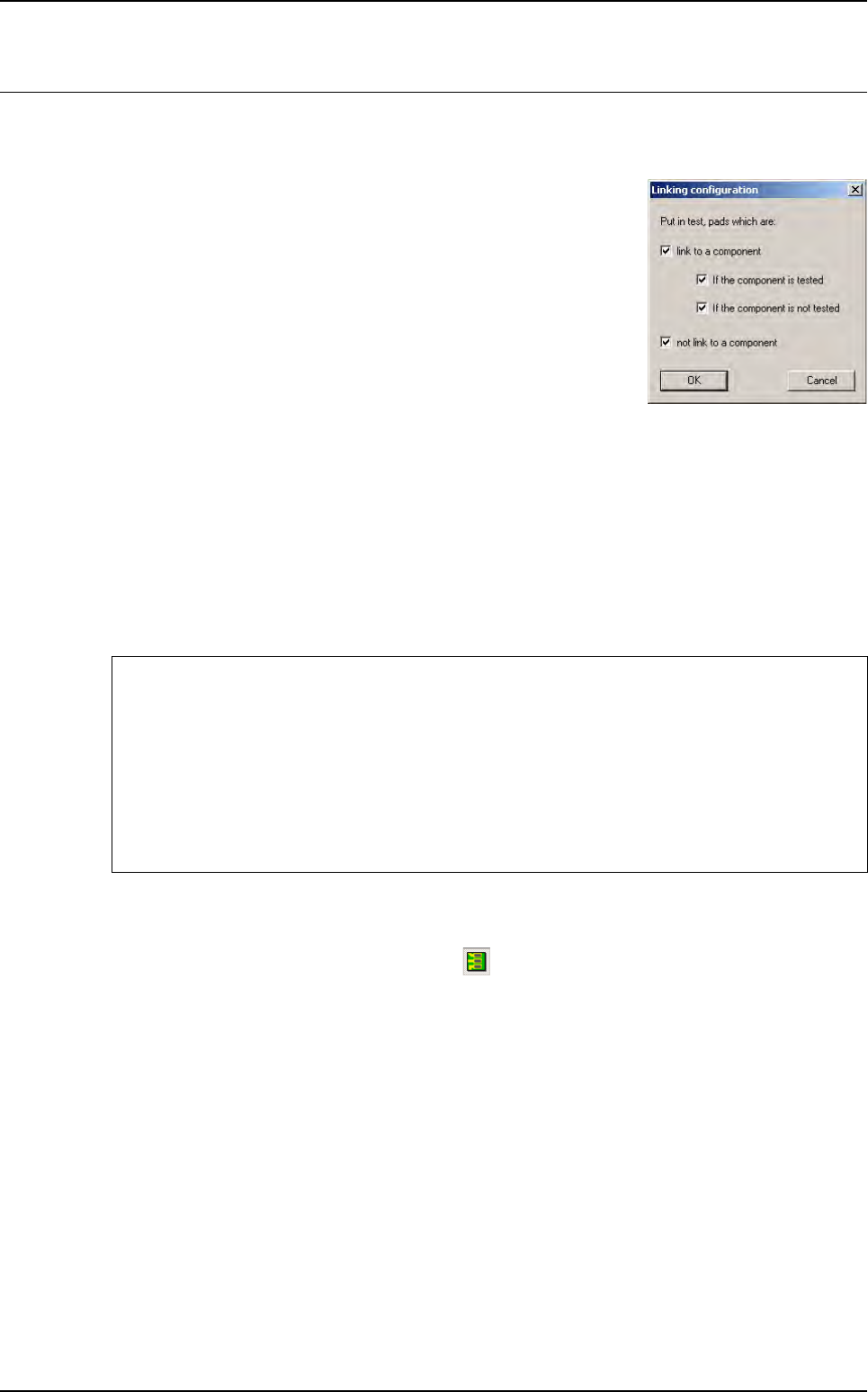
9.2.2 Link pads to components
After linking the paste pads to components, you can choose to test some of the paste pads using
the precedent dialogue box.
This function enables a paste pad to be linked to its component. Directly after import, the paste
pads are all named arbitrarily.
The names are of the following type:
Jedec: C#5104 Topology: C#4217
9.2.3 Color code
To display the paste pads, click on this icon in the tool bar.
Yellow: paste pad tested and linked to a zone.
Green: paste pad tested and not linked to a zone.
Red: paste pad not tested and not linked to a zone.
Purple: paste pad not tested and linked to a zone.
After Link pad to component the pads can be re-named in 2 ways:
If no paste pad has been associated with a component
Jedec: pPaste Topology:p#2159
The paste pad has been associated with a component
Jedec: pCMP0117 Topology: pC308#2 (paste pad no. 2 for the component)
In this case, the pad has been associated with component
C308 from the CMP0117 family.
2D solder paste inspection
Vision 2007 4.10 User Manual Rev 01 9 - 5
9.3 Solder paste inspection
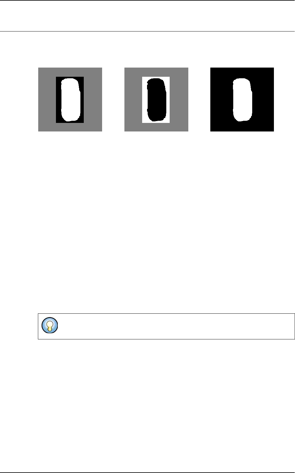
9.3.1 Image acquisition and subtraction
Blue peripheral (255) Amber axial (60)
I
mage 2 Image 1 Resulting image
Image 1:image obtained with amber axial lighting.
Image 2: enhanced image obtained with blue peripheral lighting. This enhancement is performed
to enable inspection of different types of PCB.
Resulting image: resulting image (2 - 1) from which the noise has been eliminated.
9.3.2 Processing
The solder paste is searched for using blob on the resulting image. The blob is a processing tool
which enables search of a shape or spot characterized by a number of pixels (shape size) and
one transition threshold (shape brightness) in gray level.
The blob searches within an area defined by: reception pad area + sidewalk.
The blob returns the surfaces and positions of the centers of gravity of the 20 largest spots found.
If the center of gravity of a spot found is outside the reception pad, the spot is excluded from the
results. The surfaces of the resulting spots are added together and the center of gravity of the
assembly formed by all the spots is calculated.
S = S1+S2+…+S20
X = ( S1X1+S2X2+…+S20X20 )/( S1+S2+…+S20 )
Y = ( S1Y1+S2Y2+…+S20Y20 )/( S1+S2+…+S20 )
If the blob finds something, a final test is performed, which is a histogram to validate that the
blob found the paste. The histogram is placed at the coordinates that the blob returned and its
surface is equal to a percentage of the theoretical surface.
If the histogram validates the paste presence, then the results are returned. Otherwise, a sur-
face fault is returned for the paste.
This sum enables calculation of a weighted center of gravity when the pads are cut for
all parts forming the solder paste pad.
=-