VI User Manual.pdf - 第204页
Tools library 7 - 42 Vision 2007 4.10 User Manual Re v 01 Individual lead setting: choi ce of the lead by choosing his location on the component side ( A ), and the which one number on this side. Individual histogram set…
Tools library
Vision 2007 4.10 User Manual Rev 01 7 - 41
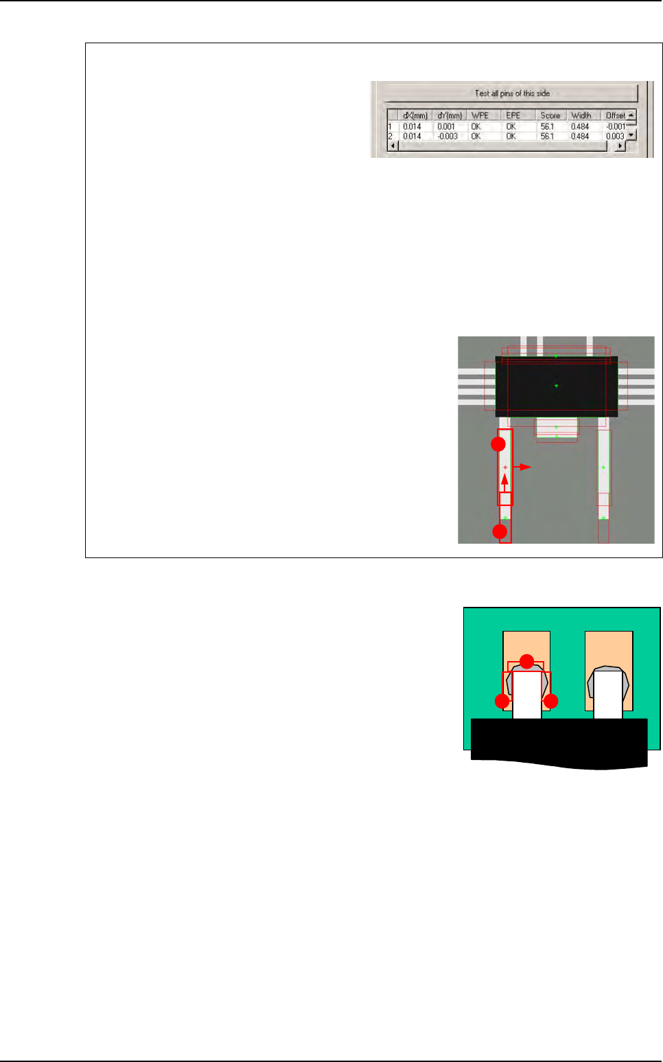
7.8.5 Solder joints detection
We can detect this flux by placing histograms in top of the
solder joint. There are 3 locations around the lead where the
weld could be inspected:
A End of lead,
B Right side,
C Left side.
One side test
Click on Test all pins of this area button to
test all the pins of one side.
dX & Y(mm): lead position deviation.
WPE: success of the edge for the width de-
tection.
EPE: success of the edge for the end of lead detection.
Score: average of the 2 scores.
Width: width computed by the double Edge.
Offset: lateral offset of the double edge from the center of the edge window.
Test results
A
Edges pin detection: edge double.
B End of pin detection: simple edge.
A
B
A
BC
Custom
Tools library
7 - 42 Vision 2007 4.10 User Manual Rev 01
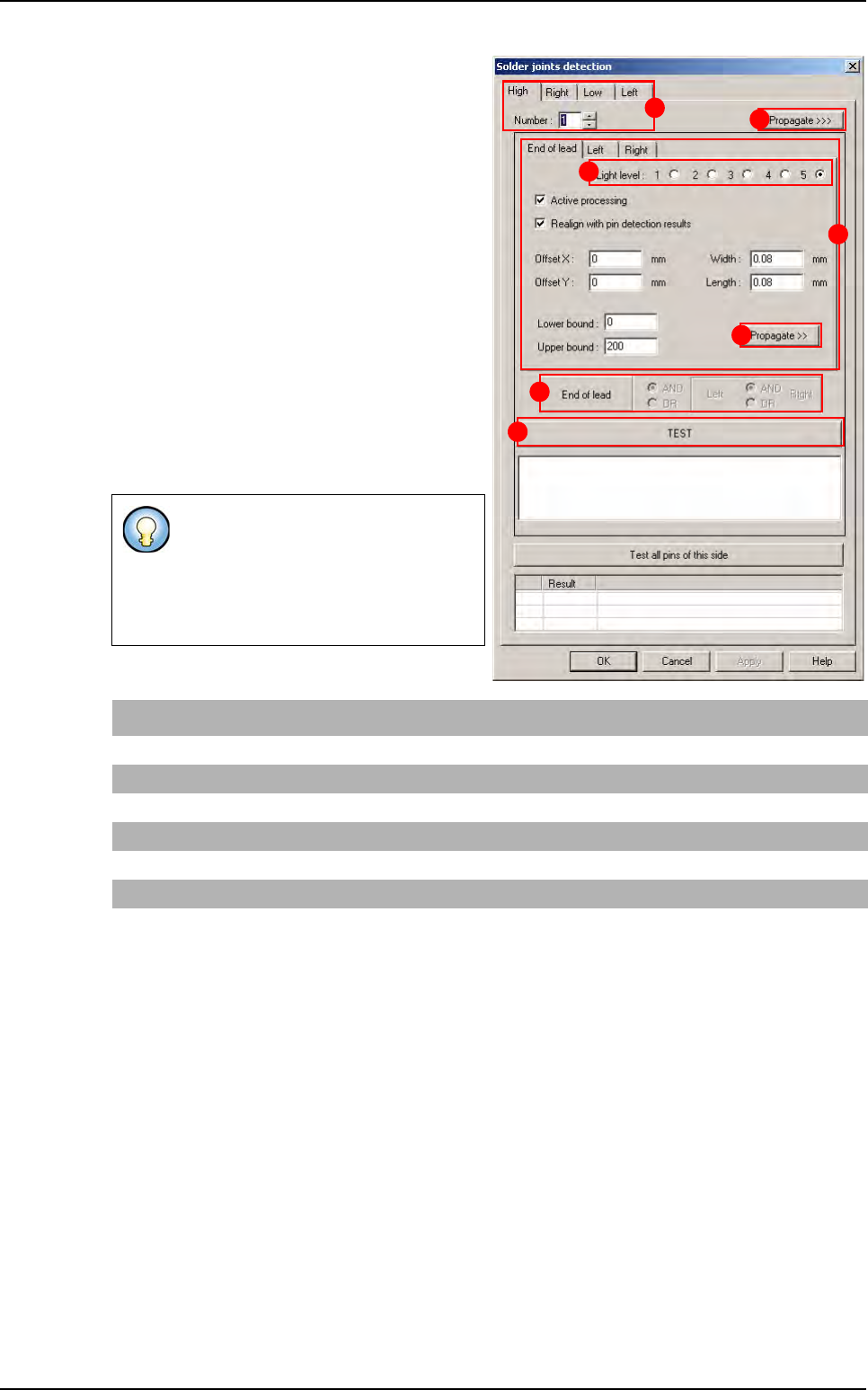
Individual lead setting: choice of the lead by
choosing his location on the component side
(
A), and the which one number on this side.
Individual histogram setting: select the lead
side (
B) tab to set the wanted histogram.
Select the
Light level (C): each histogram can
have its own light level.
In
End of lead AND/OR left AND/OR right (D)
specify the global test result definition.
Press
TEST (E) button to test and display the 3
histograms results.
Press
Propagate >> (F) button (in the lead side
tab) to propagate the parameters to the 3 histo-
grams: end of lead, left and right.
Press
Propagate >>> (G) button (in the com-
ponent side tab) to propagate the parameters
to all the leads and all the sides.
3 histograms are used to detect joint
around the lead.
You can specify the global joint test re-
sult according to these three one: it is
a boolean function.
End of lead histo First operator Left histo Second operator Right histo Global result
OK AND (NOT OK OR OK) = OK
OK AND (NOT OK AND OK) = NOT OK
NOT OK AND (NOT OK OR OK) = NOT OK
NOT OK OR (OK AND OK) = OK
NOT OK OR (NOT OK AND OK) = NOT OK
NOT OK OR (NOT OK OR OK) = OK
A
B
C
D
E
F
G
Custom
Tools library
Vision 2007 4.10 User Manual Rev 01 7 - 43
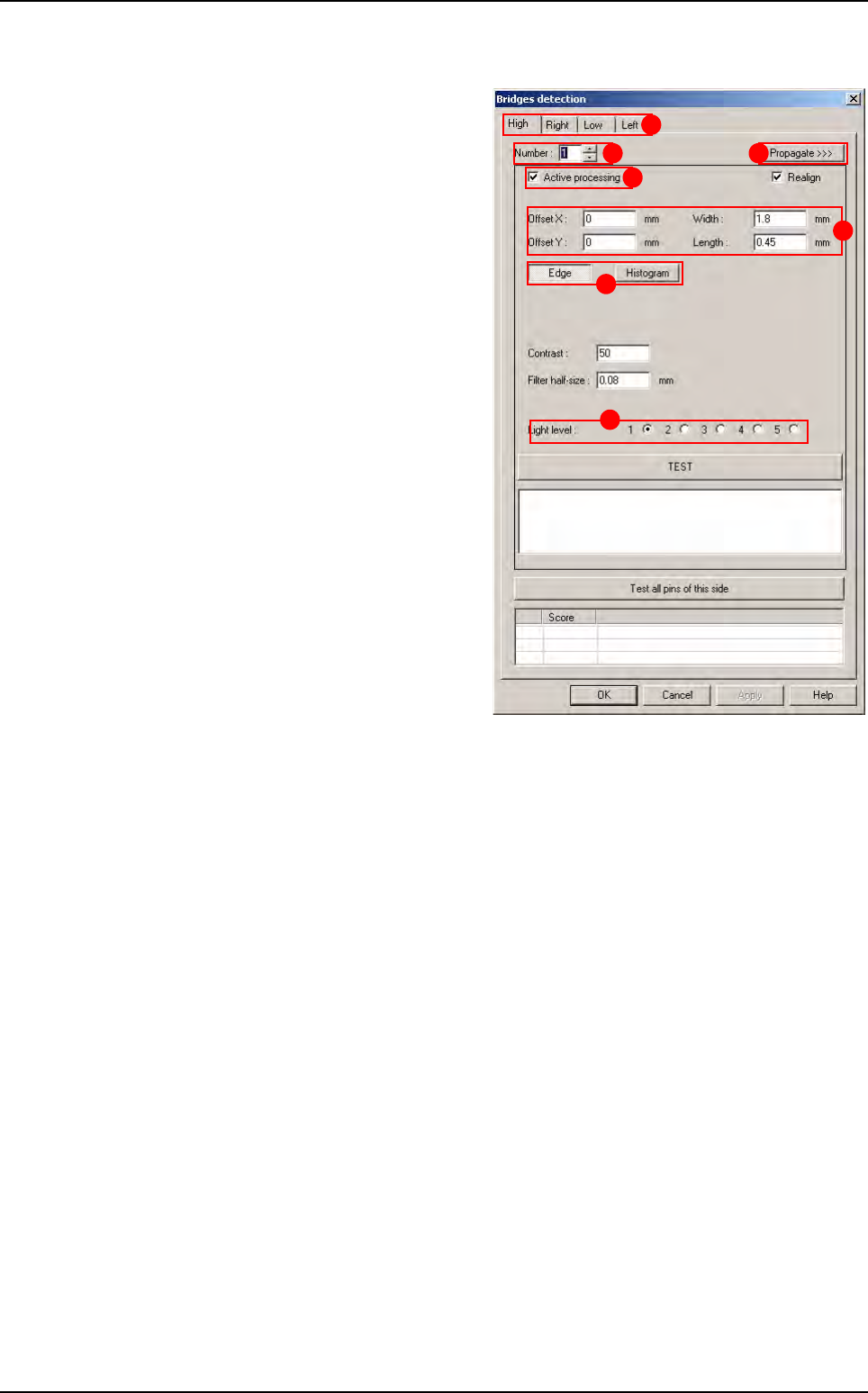
7.8.6 Bridges inspection
Bridges inspection uses histograms or edges
placed between 2 leads. Each bridge inspec-
tion can have individual parameters and can be
active or not.
Select the tab (
A) of the component side to edit.
In
Number
(
B
), select the bridge number to edit.
Tick Active processing (C) to run the bridge
inspection,
Change, if necessary, in
Offset X & Y, Width
and Length (D) the tool window size and posi-
tion,
Choose to use an
Edge or an Histogram (E) to
check the solder bridge,
In
Light level (F) select the light level to use.
Press
Propagate >>> (G) button to propagate
the parameters to all the leads and all the
sides.
A
B
C
D
E
F
G
Custom