VI User Manual.pdf - 第92页
.TST file creation 4 - 18 Vision 2007 4.10 User Manual Re v 01 4.6 Creation result The .tst file obtained is a representation of the p ane l with all its compon ents and fiducials that are ac- cessible by click ing on th…
.TST file creation
Vision 2007 4.10 User Manual Rev 01 4 - 17
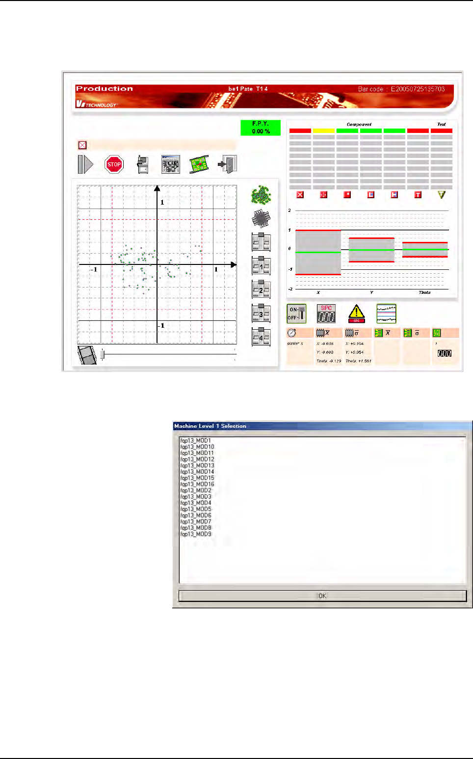
4.5.4 Production screen
You can retrieve these levels in the production screen, on the scatter chart.
Selecting one of Machine or Level ... buttons will display the list of the available feeder informa-
tion.
In Machine Level Se-
lection window, select-
ing some of the lines will
only display (on the
scatter chart) the rela-
tive information: compo-
nents placed by
selected machine.
Feeder information
.TST file creation
4 - 18 Vision 2007 4.10 User Manual Rev 01
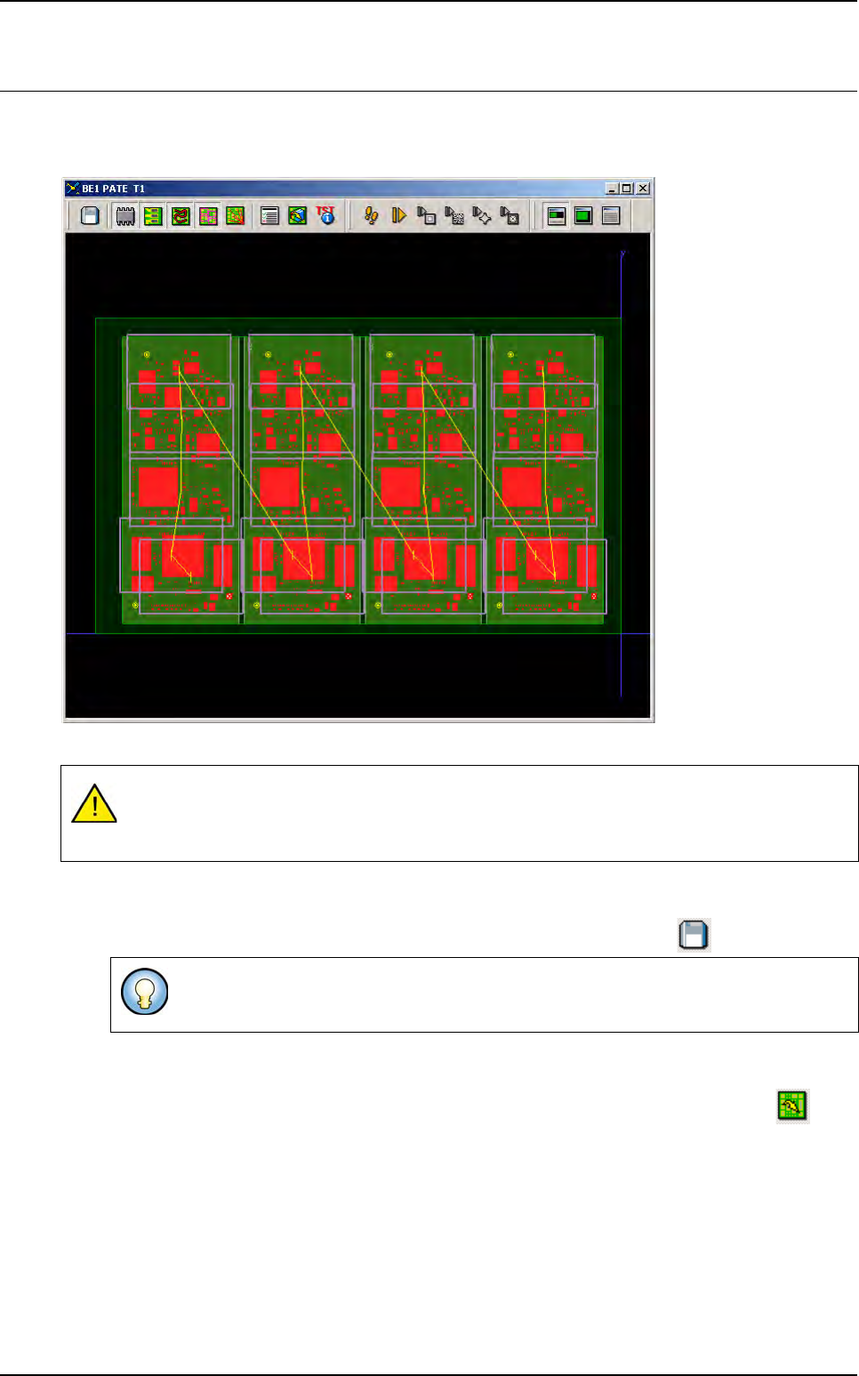
4.6 Creation result
The .tst file obtained is a representation of the panel with all its components and fiducials that are ac-
cessible by clicking on them.
The panel can now be inspected by the machine, both in the production and debug mode.
4.6.1 Saving the .tst file created
Select Save or Save as in the Test file menu, or click on the Save icon in the tool bar.
4.6.2 Opening and closing an existing .tst file
Select Open test file (Ctrl+I) in the Process menu, or click on the Open .tst file icon in the
tool bar.
If a .tst file is already open, the Open .tst file function is available in the Test file menu. Select
Open test file in the Test file menu.
Vision 2007 will ask you to select a .tst file. The default directory is always: C:\VIT\Data. By de-
fault, Vision 2007 presents the .tst files. Double click on the selected .tst file or press Open in
order to view it on the screen.
Press Close from the Test file menu in order to close a Process Test window.
A visual inspection comparing your panel with its graphic representation ensures that inspec-
tion is not carried out using an incorrect .tst file, resulting in inspection (position) errors stem-
ming from the .tst file.
By default, the file will take the name of the panel (PANEL_NAME of the .vis file used
for creation).
.TST file creation
Vision 2007 4.10 User Manual Rev 01 4 - 19
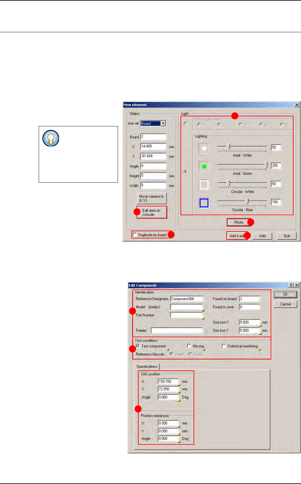
4.7 New element creation
Once the .tst file is created, new elements can still be added: components, pad, connector, text, trace,
datamatrix or barcode, skip and zones.
4.7.1 Create a component
1. Open a .tst file then load the corresponding panel.
2. In Edit menu select Component, then Add a Component to open New element window.
3. The window New element
appears after the fiducials in-
spection.
4. Define the lighting level
(A), take a photo if needed
by clicking on Photo button
(B).
5. Define the position of the
component by clicking on the
.tst file, then adjust the com-
ponent location with the Edit area on console button (C).
6.
You can duplicate the component creation by board by picking the option
Duplicate by board
(
D
).
7. Click on Add & edit button (E): the Edit Component window is displayed.
8. The Identification parame-
ters can be set on the A part.
9. The Test conditions can be
selected in the B part.
10. The CAD position param-
eters can be modified in the
Specifications tab (C).
11. The modifications can be
applied by clicking on OK but-
ton, or discarded by clicking on
Cancel button.
If fiducials are not
correctly acquired a
shorter version of
the New element
window is
displayed
.
A
B
C
D
E
A
B
C