VI User Manual.pdf - 第407页
.ini files Vision 2007 4.10 User Manua l Rev 01 A - 31 A.5.17 Custom tool: solder bridge detection INI section : [Cust om(Bridge)] B This value is used to compute the bridge detection width parameter. Width = pin width *…
.ini files
A - 30 Vision 2007 4.10 User Manual Rev 01
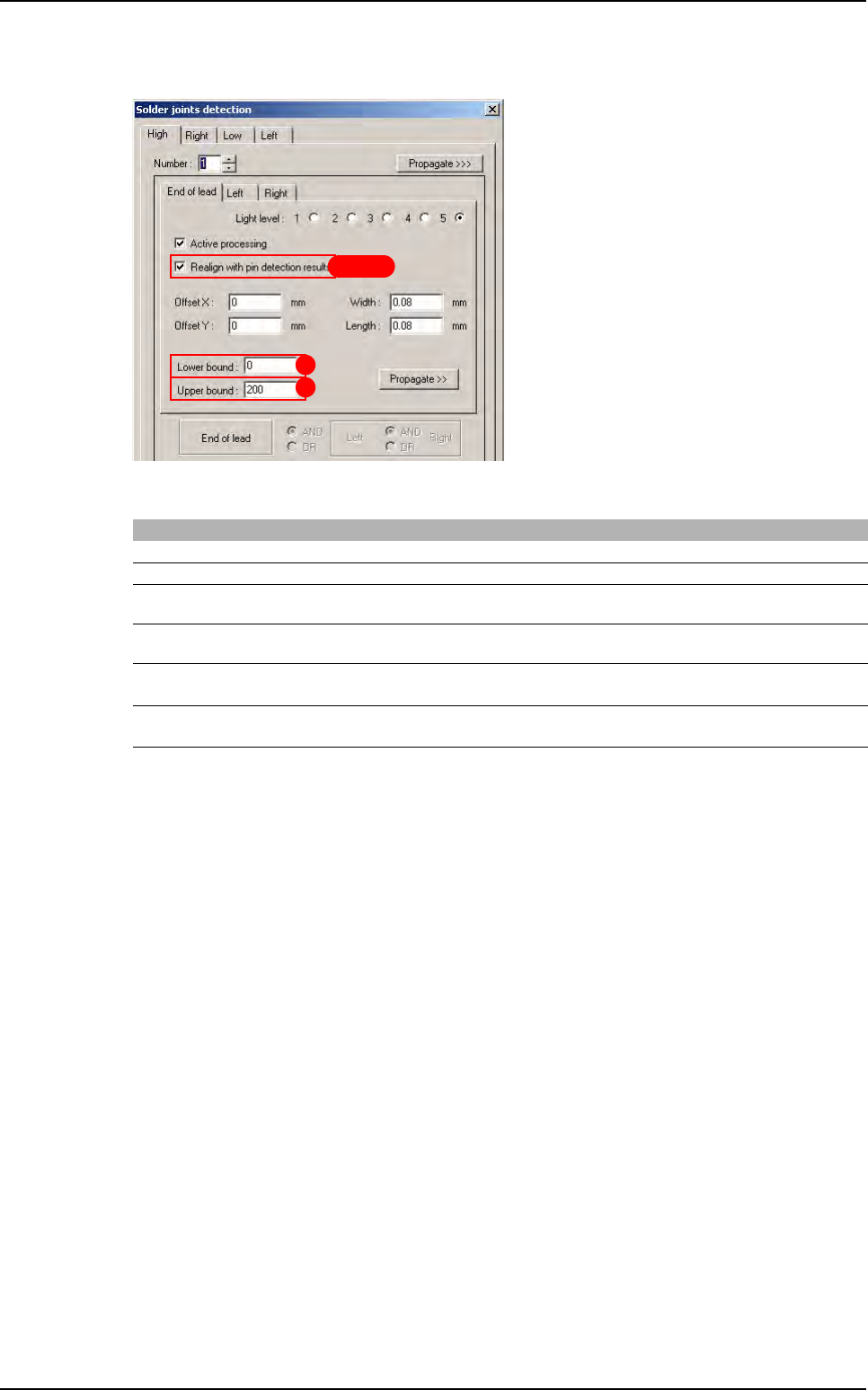
A.5.16 Custom tool: solder joints detection
INI section : [Custom(Joint)]
C, D, E and F are used to realigne joint with pin detection
Mark Key name Initial value Min value Max value
A Min Value 0 0 255
B Max Value 200 0 255
C Body Position to use
(0:CAO, 1:Body detection, 2:LeadsAverage)
002
D Body Position to use if body detection is not available
(0:CAO, 1:LeadsAverage)
001
E
Angle to use when recal is activated
(0:CAD, 1:Body Detection, 2:LeadsAverage)
102
F
Angle to use when recal is desactivated
(0:CAD, 1:Body Detection, 2:LeadsAverage)
102
B
A
C D E F
Library default values
.ini files
Vision 2007 4.10 User Manual Rev 01 A - 31
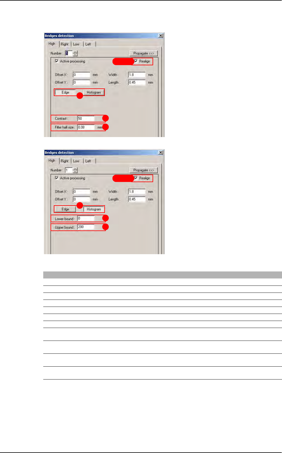
A.5.17 Custom tool: solder bridge detection
INI section : [Custom(Bridge)]
B This value is used to compute the bridge detection width parameter. Width = pin width * B
C This value is used to compute the bridge detection length parameter. Length = pin length* C
H, I, J and K are used to realign bridges with pin detection
Mark Key name Initial value Min value Max value
A Use edge 1 0 1
B Width margin 0.9 0 5
C Height margin 0.5 0 5
D Contrast 50 0 255
E Filter half size 0.08 0.03 1
F Min Value 0 0 255
G Max Value 200 0 255
H Body position to use
(0:CAO, 1:Bodt Detection, 2:LeadsAverage)
002
I Body position to use if body detection is not available
(0:CAO, 1:LeadsAverage)
101
J Angle to use when recal is activated
(0:CAD, 1:Body Detection, 2:LeadsAverage)
102
K Angle to use when recal is desactivated
(0:CAD, 1:Body detection, 2:LeadsAverage)
002
E
D
H I J K
A
H I J K
A
E
D
Library default values
.ini files
A - 32 Vision 2007 4.10 User Manual Rev 01
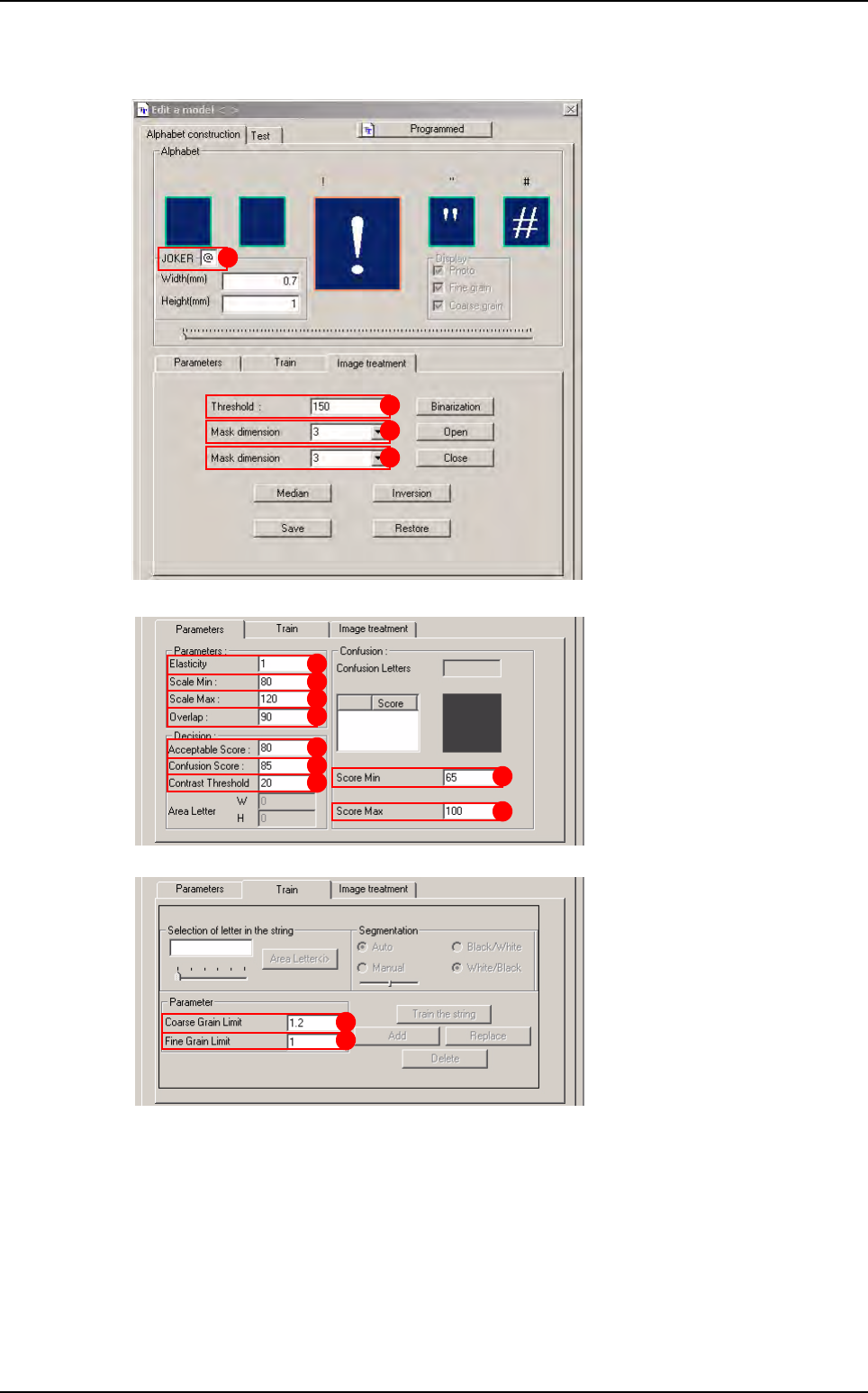
A.5.18 OCV fonts
A
D
E
F
K
L
M
N
G
O
J
P
Q
S
R
Library default values