VI User Manual.pdf - 第145页
Match Maker Vision 2007 4.10 User Manua l Rev 01 6 - 11 6.4.3 S t ep 2: Component definition This second step e nables to define the geometr y of the compone nt by using the image of the camera. Severa l st eps are neces…
Match Maker
6 - 10 Vision 2007 4.10 User Manual Rev 01
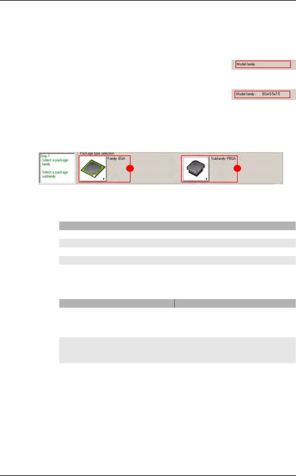
6.4.1.4 Model family
The field can be empty or indicate a reference:
The field is empty
The
Part Number
is not linked to a model in the Standard Library.
The field is not empty
The Part Number is linked to a model in the Standard Library.
Match Maker has been realized for this Part Number.
6.4.2 Step 1: Package type selection
This first step enables to choose the Package family (A) and the Package subfamily (B) which
correspond more to the selected Part Number.
The status of the Step 1 (black, red, green) depends of the actions realized.
6.4.2.1 Case 1: Black or red Step 1
6.4.2.2
Case 2: Green Step 1
The Package family is composed of five families and the Cancel button.
Each family has a Cancel and None button.
State Action
The Package family button is activated
Choose a
Package family.
A Package family is selected Select a Package subfamily or go to step 2.
The Package subfamily button is activated Choose a Package subfamily or go to Step 2.
The Package subfamily button is not activated Choose a Package family.
A Package subfamily is selected Go to Step 2.
State Information
A
Package family
is selected a Standard Library Model is loaded.
it is possible to change:
- the Package family
- the Package subfamily
The Package subfamily button is active a Standard Library Model is loaded
it is possible to change the Package family
it is possible to choose a Package subfamily.
A Package subfamily is selected a Standard Library Model is loaded
it is possible to change:
- the Package family
- the Package subfamily.
A B
Match Maker graphical user interface
Match Maker
Vision 2007 4.10 User Manual Rev 01 6 - 11
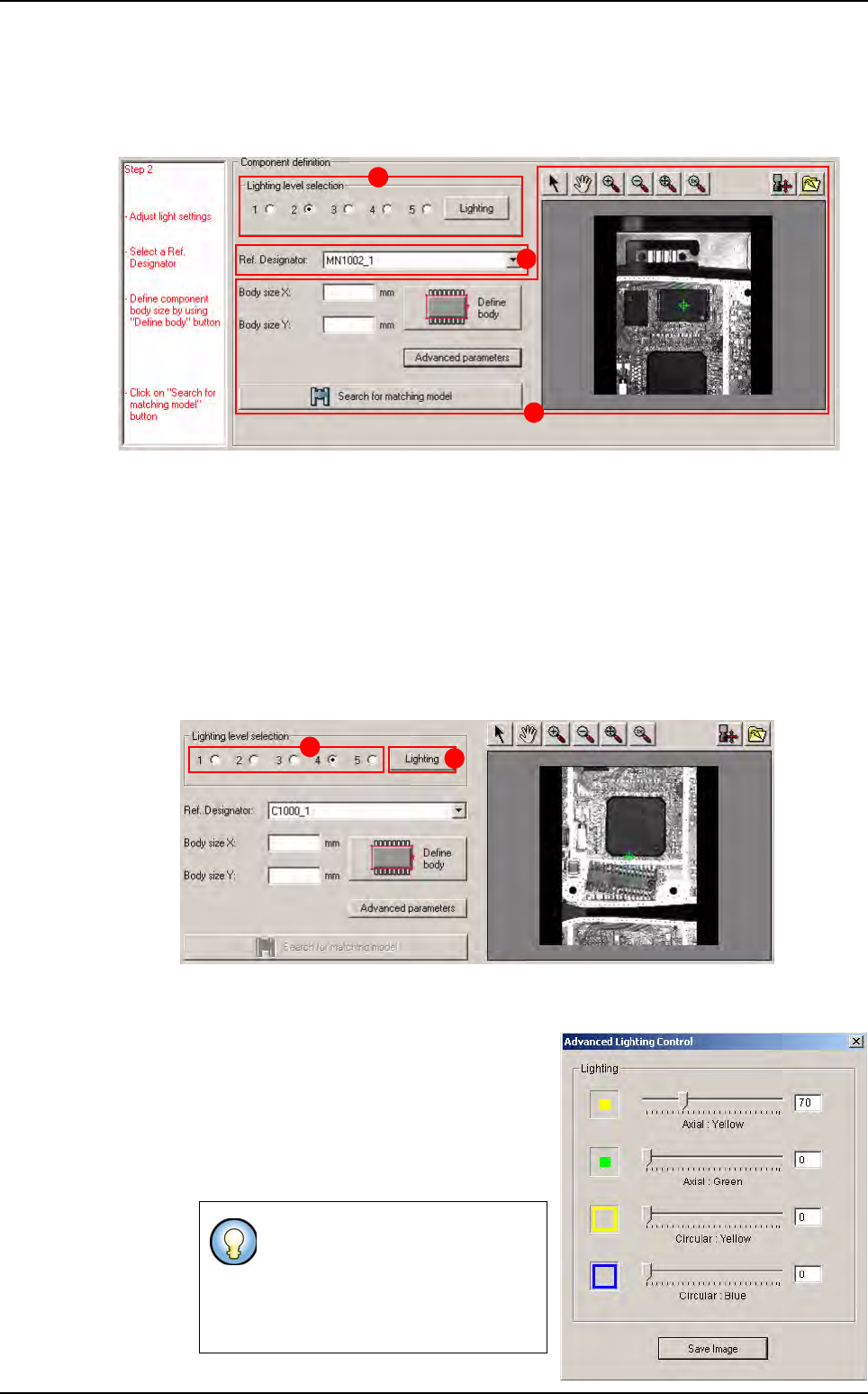
6.4.3 Step 2: Component definition
This second step enables to define the geometry of the component by using the image of the
camera. Several steps are necessary:
Lighting level selection (A): to define geometry of the unknown component, adjust lighting in
order to observe the shape of the component correctly.
Reference Designator selection (B): to select an image where the user observes the shape
of the component correctly to help him in the definition of the body.
Component Body size definition (C): to define the geometry of the component. Search for
matching model.
6.4.3.1 Lighting level selection
2 types of lighting can be chosen:
Standard lighting (A): lighting defined by default (1 to 5), located in a default.ini file.
Select a lighting level, then the picture is refreshed with the lighting level.
Specific lighting: lighting with axial and cir-
cular adjustments of intensity. Click on the
Lighting button (B). The
Advanced Light-
ing Control
window appears.
Set the lightings and close the window, then
the picture is refreshed and the radio but-
tons are all empty.
In the
Advanced Lighting Control
window, it is possible to save the
image of the component with this
specific lighting by clicking on
Save Image. It is useful for re-use
on offline station.
A
B
C
A
B
Match Maker graphical user interface
Match Maker
6 - 12 Vision 2007 4.10 User Manual Rev 01
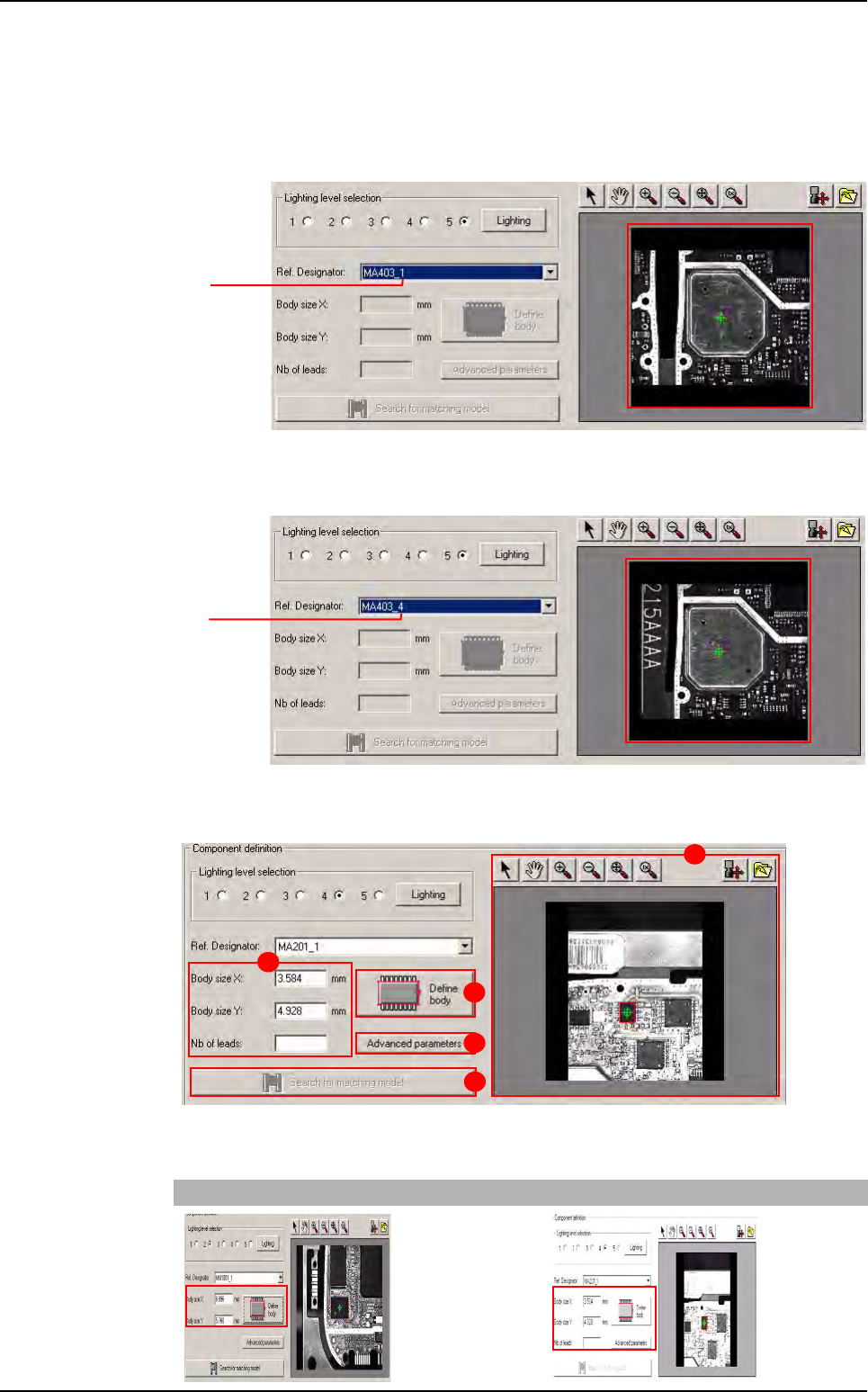
6.4.3.2 Reference designator selection
This combo displays the list of the reference designators related to the current Part Number.
While a reference is selected, the camera moves to the selected component on the panel.
1. A Reference Designator is selected, the component appears to the screen.
2. Select a new Reference Designator, the camera moves towards the new component.
6.4.3.3 Component body size definition - Search for matching model
The component body size definition is composed of:
Body size fields (A), two cases:
Family without leads Family with leads
Board 1
Board 4
A
B
D
C
E
Match Maker graphical user interface