VI User Manual.pdf - 第234页
Tools library 7 - 72 Vision 2007 4.10 User Manual Re v 01 7.11.7.2 Component’s leads detection When you increase the lead num- ber ( A ), the corresponding su b zone is automatically displayed on the camera disp lay. Pre…
Tools library
Vision 2007 4.10 User Manual Rev 01 7 - 71
7.11.6 Custom tool for multizones model
The custom tool requires specific sub zones which are only used for this inspection. When
selecting the custom tool, the sub zones are automatically computed. In the custom tool for
multizones:
The body detection is done on 2 opposite
corners with 2 perpendicular helicopter
edges.
The component position and presence
is only computed with the body detec-
tion and not leads detection.
Only joints tools are realigned with the leads position. The bridges tools are realigned with
the body position.
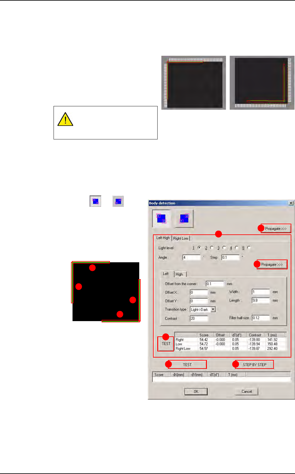
7.11.7 Custom tool edition
7.11.7.1 Body detection
Press or button
to select the corners to use
for body detection.
In
Left Hight and Right
Low
(A) tabs the parame-
ters of the 4 rotating edges
are displayed.
Press
Propagate >>> (B)
button to propagate the pa-
rameters to the opposite
corner (Left/High sides on
this example).
Press
Propagate >>> (C)
button (in the tab) to propa-
gate the parameters to the
second edge of the same
corner (Right side on this
example).
Press
TEST (D) button (in the tab) to test the 2 rotating edges of the current corner.
Press
TEST (E) button to test the 4 rotating edges of the 2 corners.
Press
STEP BY STEP (F) button to test the 4 rotating edges of the 2 corners step
by step.
If no lead is detected on one
side, it does not return miss-
ing component.
A
B
C
D
E F
3
4
1
2
Multizones
Tools library
7 - 72 Vision 2007 4.10 User Manual Rev 01
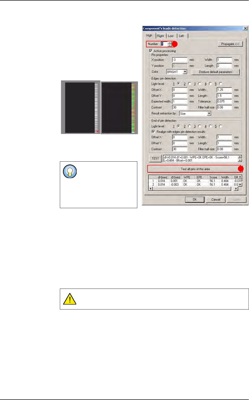
7.11.7.2 Component’s leads detection
When you increase the lead num-
ber (
A), the corresponding sub
zone is automatically displayed on
the camera display.
Press
Test all pins of this area
(B) button to test all the leads of
the sub zone displayed.
Result of the one lead test Result of all area’s
leads
7.11.8 Custom tool execution
7.11.8.1 Execution of one reference
Ctrl + E is the only way to debug your model on a real picture,
It takes pictures of each sub zones with the 5 light levels to ensure the changes,
It runs all the links and takes the number of pictures required.
7.11.8.2 Global execution
All the required pictures are taken for each link.
Some of the leads dis-
played on this picture
may be tested on the
following sub zone. That
is why you can not see
their test results.
Multizones are very time consuming.
A
B
Multizones
Tools library
Vision 2007 4.10 User Manual Rev 01 7 - 73
7.12 Data Matrix
7.12.1 Description
Data Matrix are 2D codes used for board identification. With the AOI system, there are difer-
ent way to read Data matrix according to the application:
Using the internal camera,
Using an external camera,
Using an external 2D scanner (no library model is needed).
7.12.2 Data Matrix using the internal camera
7.12.2.1 Data Matrix creation
Load the .tst file in which you need to create Data Matrix. Load a board with the Data
Matrix in the machine. With the .tst file active, go in
Edit menu, and in Board sub
menu, select
Create Data Matrix. This starts the Data Matrix creation Wizard.
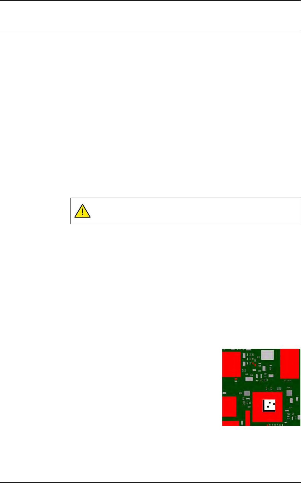
Edition of Data Matrix area
1. Click in the CAD representation to move the camera to the Data Matrix location on
the panel.
2. Press the Edit area button and adjust the area around the Data Matrix in the cam-
era real image.
3. Enter the CAD angle of the Data Matrix in the Theta field.
4. Press Next.
Description of the new Data Matrix
1.
Enter the reference designator of the Data Matrix and the name of the library model.
2. If the board number is not the right one, select the board number (or Panel) from
the drop down list.
3. To propagate the Data Matrix to all the boards, tick the check box.
4. Press Next.
Image capture for the library
1. Adjust the lights to obtain a good contrast.
2. Press Image capture for the library button and save
the Data Matrix image.
3. Press Finish.
4. The Data Matrix appears in the CAD representation.
Repeat this operation until you see the Data Matrix code on the camera pic-
ture.