VI User Manual.pdf - 第244页
Tools library 7 - 82 Vision 2007 4.10 User Manual Re v 01 7.14 Blob 7.14.1 Blob tool definition The Blob tool detects random shap es based on the gray levels in the image. It identifies groups of pixels that fall into a …
Tools library
Vision 2007 4.10 User Manual Rev 01 7 - 81
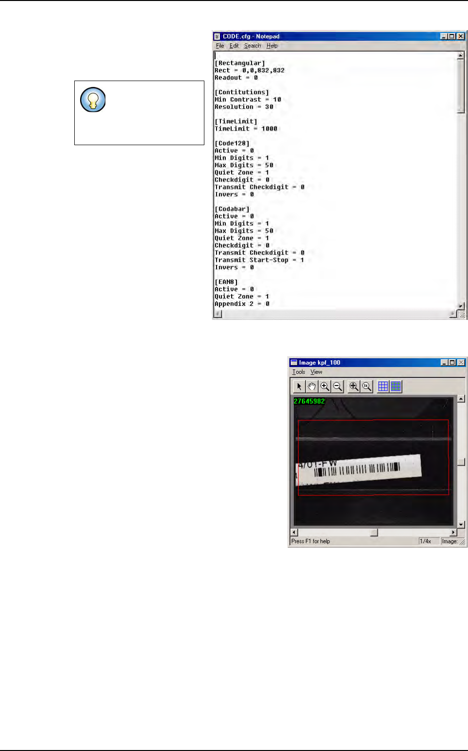
4. In Import / Export configu-
ration file
(E) section, you can
choose to import or export a
configuration file (.cfg file).
5. Press Test (F) button to
lauch the Data Matrix reading test. The standard result
(score, XY position, theta, ...)
and the
decoded character string are displayed.
You can also see the result in the COGNEX con-
sole.
The .cfg file contain
bar code coding
type parameters. It
is an ASCII file.
Bar code CVB model
Tools library
7 - 82 Vision 2007 4.10 User Manual Rev 01
7.14 Blob
7.14.1 Blob tool definition
The Blob tool detects random shapes based on the gray levels in the image. It identifies
groups of pixels that fall into a user defined gray scale range. Several parameters allow
shape-based filtering.
The Blob tool is used to find contrasted objects, when the object shape is not known precisely.
It can find pin tips for backplane or connector inspection, polarity marks, solder defects as pin-
holes, missing or excess solder, or various PCB pollution... It returns presence, X, Y and The-
ta position of the biggest found shape. Blob runs in several steps:
7.14.1.1 Segmentation
This step determines which pixels are object pixels or background pixels. Two types
of segmentations are available:
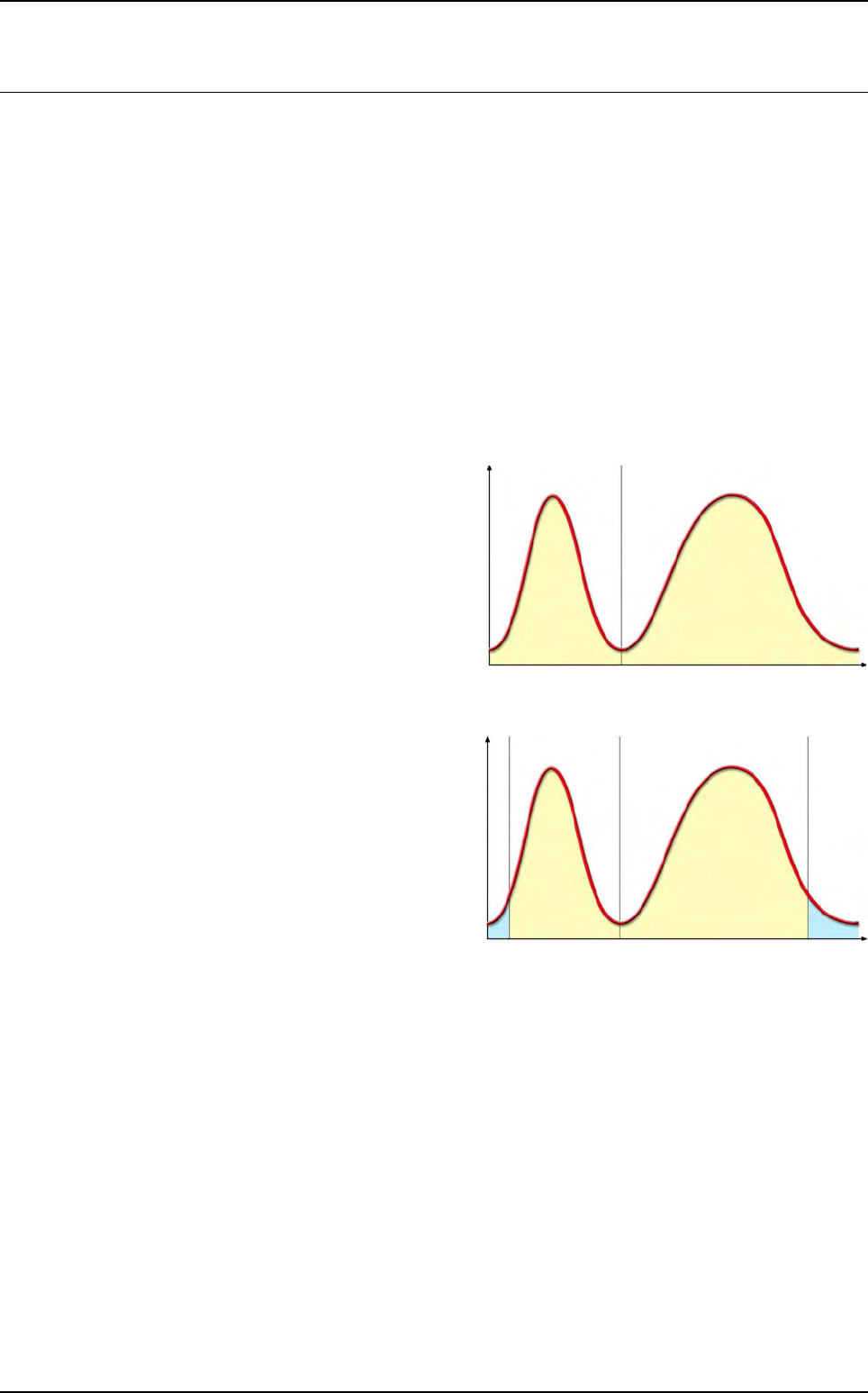
Fixed thresholding
The division between object
and background pixels is deter-
mined by a gray level value
Relative thresholding
The threshold is computed ac-
cording to the values of all the
pixels in the search area. 2 “tail”
parameters represent the per-
centage of noise-level pixels
that are excluded from the
threshold calculation. The
threshold is a percentage of the
gray levels range without the
tails.
7.14.1.2 Masking
The Blob can apply a mask that will exclude some portions of the segmented image.
The mask is a binary bitmap image. The center of this bitmap is realigned with the
center of the tool’s search area. Pixels of the segmented image covered with the
mask’s black pixels won’t be analyzed.
7.14.1.3 Blob analysis
The tool finds groups of pixels in the segmented and masked image. It returns vari-
ous shape parameters that tend to describe the shape features: Area, Acircularity,
Elongation, Angle.
Area
The area is the number of pixels included in the shape, multiplied by the area of a
single pixel (X pixel size * Y pixel size).
From now on, the blob search area is adapted to pad with angles: a mask is applied
to the search area to simulate the search area rotation. The sidewalk has then to be
set (set to 0 by default by the customers to avoid false defects).
0255Gray levels
N
u
m
b
e
r
o
f
p
i
x
e
l
s
Threshold
Background Object
0255Gra
y
levels
Low tail High tail
N
u
m
b
e
r
o
f
p
i
x
e
ls
Threshold
Background Object
Tools library
Vision 2007 4.10 User Manual Rev 01 7 - 83
Acircularity
The Acircularity is the deviation of the radius values of the blob from the radius of a
circle that has an equivalent area.
Elongation
The Elongation is the ratio of the dispersion along the minor blob axis to the disper-
sion along the major blob axis.
Angle
The blob angle is the angle of its major axis with respect to the horizontal axis.
7.14.1.4 Filtering and sorting
User-defined criteria for each of the above parameters enable filtering the results.
7.14.2 Model description tab
1. On the Model description tab, in the Edit a model window, choose the processing: Blob.
A new
Blob tab appears behind the Model description tab.
2. Click Auto area button to place the model encompassing area exactly on the image.
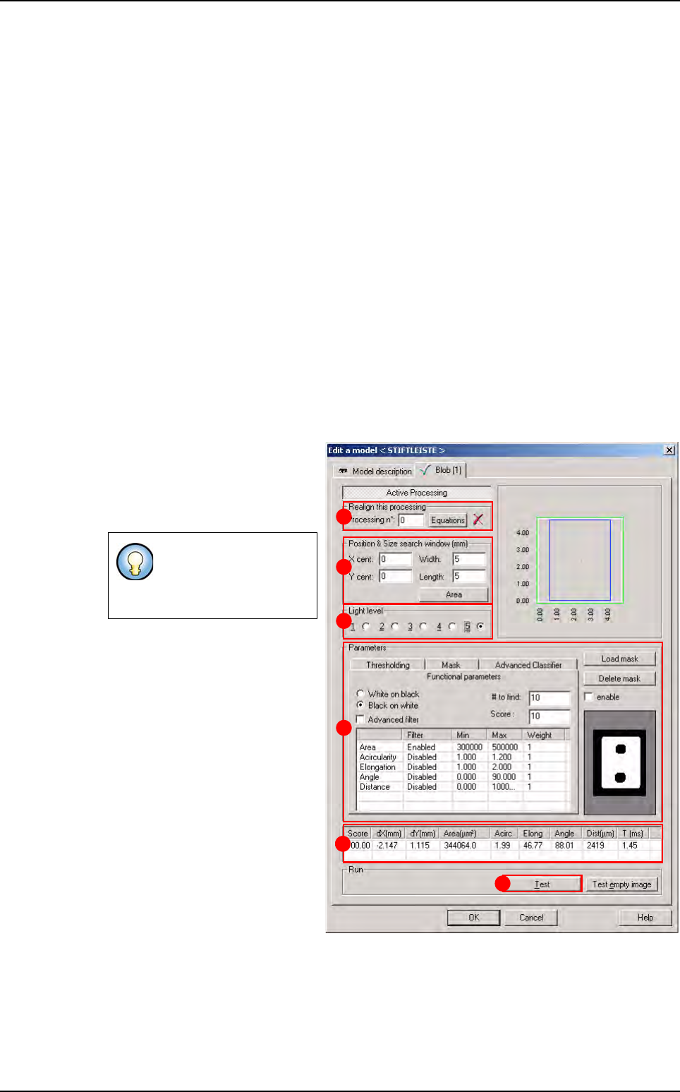
7.14.3 Blob tab
1.
Use
Realign this processing
(
A
) section
if you want to realign
the position of the tool with anoth-
er one (not available for window
1).
2. In Position & Size search
window (mm)
(B) section, enter
the size and position of the search
window (zone in which the feature
will be searched for).
3.
In
Light level
(
C
)
section, s
elect
the light level you want to use.
4. In Parameters (D) section, en-
ter the Blob tool parameters (see
below
7.12.3.1 Blob parame-
ters
).
5. Click Test (E) button to test the
Blob tool and display the results
(see below
7.12.3.2 Blob test).
The result show in the table (
F).
7.14.3.1 Blob parameters
Thresholding tab
If you need a special
equation to realign, you
can do so using the
Equations button.
A
B
C
D
E
F
Blob