VI User Manual.pdf - 第206页
Tools library 7 - 44 Vision 2007 4.10 User Manual Re v 01 7.9 Profiler ™ in Custom The Profiler ™ tool, included in the Custom tool is used to detect th e lifted leads and bad joints. The meth od is based on the analysis…
Tools library
Vision 2007 4.10 User Manual Rev 01 7 - 43
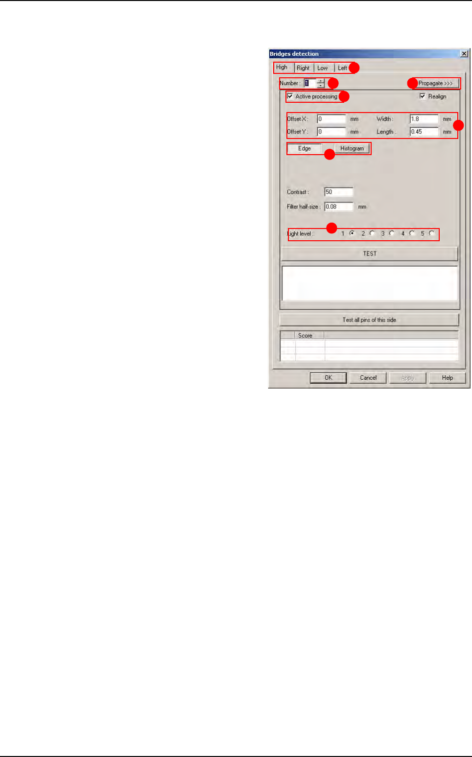
7.8.6 Bridges inspection
Bridges inspection uses histograms or edges
placed between 2 leads. Each bridge inspec-
tion can have individual parameters and can be
active or not.
Select the tab (
A) of the component side to edit.
In
Number
(
B
), select the bridge number to edit.
Tick Active processing (C) to run the bridge
inspection,
Change, if necessary, in
Offset X & Y, Width
and Length (D) the tool window size and posi-
tion,
Choose to use an
Edge or an Histogram (E) to
check the solder bridge,
In
Light level (F) select the light level to use.
Press
Propagate >>> (G) button to propagate
the parameters to all the leads and all the
sides.
A
B
C
D
E
F
G
Custom
Tools library
7 - 44 Vision 2007 4.10 User Manual Rev 01
7.9 Profiler
™
in Custom
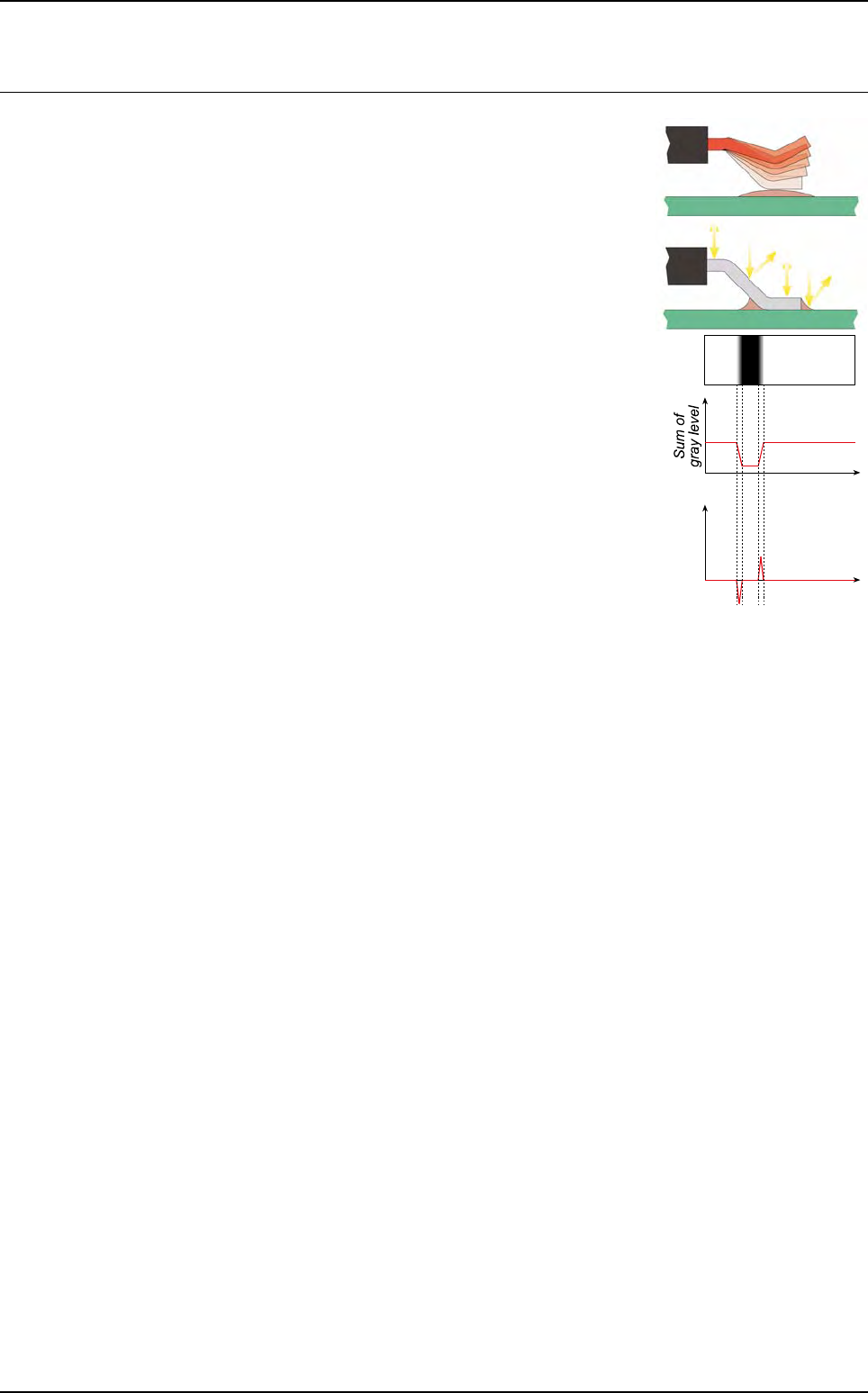
The Profiler
™
tool, included in the Custom tool is used to detect the
lifted leads and bad joints. The method is based on the analysis of
the gray level profile of each lead and joint.
When a lead is lifted, his position and his angle change. The light is
consequently reflected differently. The appearance of joint can also
change. The gray level repartition along the lead and the joint is
thus different between a lifted and a joined lead. The Profiler
™
method uses this characteristic to detect lifted leads and bad joints.
A profile is a projection onto one axis, of the gray level sum.
7.9.1 Profiler™ tool description
Profiler
™
tool works within comparison to references. Principle is to verify that profile of each
lead/joint of a component are included into tolerances.
There are 2 Profiler modes for Custom tool :
Fixed and Dynamic.
The main differences between these 2 modes are the way to set profile reference curve.
With
Dynamic mode, for each side, profile reference curve is set with profiles average of all
leads of this side. By this way, profile reference curve is set dynamically (the user does not
have to set it) and as a result, tolerances curves are set dynamically.
With
Fixed mode, the reference curve is set with profile curve of one lead. By this way, the
user has to set it manually.
For both mode, the profile reference curve for
Lead to lead is set with average of all leads of all
sides.
These 2 modes are constituted of 2 parts:
The
Global adjustment
tool, based on a global comparison of leads profile. 2 modes are available:
- Standard mode: which contains tolerance algorithm (see § 6.9.2 Profiler™ tool using)
-
Expert mode: which contains advanced algorithm
The
Lead to lead tool, based on a comparison lead with lead on a same component. This
analysis detects leads that are not similar to the other leads of the component. It allows to
take into account variations of production. On this tool, the same 2 modes (
Standard and Ex-
pert
) are available.
These 2 parts are necessary because of the variability of a production. In fact, on a same com-
ponent, welding and lead have the same aspect. On the other hand, during production, shape
of lead and aspect of welding can change.
Lead
Lead
axis
Gradient
Lead
axis
Profile
Tools library
Vision 2007 4.10 User Manual Rev 01 7 - 45
7.9.1.1 Global adjustment tool principle
This tool is based on a comparison with fixed reference (a good lead/joint). Tolerances
are constructed in relation to this reference. This reference is defined on several good
leads. For this, a reference profile is done on a good lead, and tolerances are constructed
in relation to this reference. So they are fixed for all components of a same models. Each
profile out of tolerances is considered as bad.
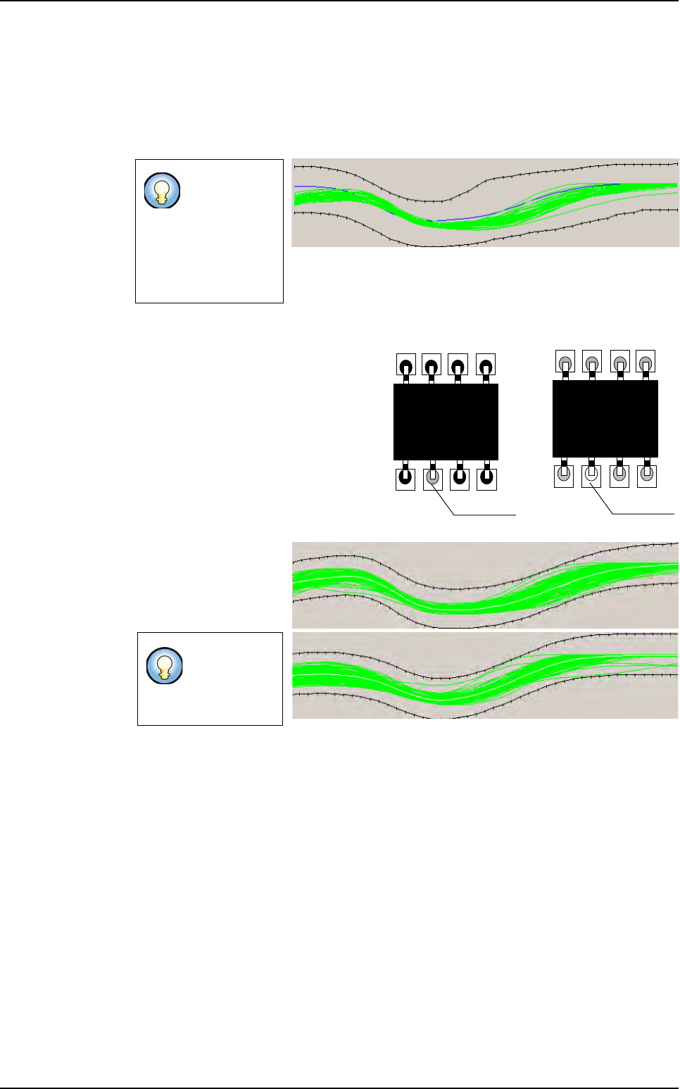
7.9.1.2 Lead to Lead tool principle
This tool allows to adapt to the variations
of aspect related to a change in the pro-
duction (aspect of the welding, aspect of
the component leads…). It is not sensi-
tive to difference between components.
For the lead to lead tool, the comparison
is with the average of all profiles of the
components.
This tool is based on a comparison with
adaptive reference.
Tolerances are auto-
matically adjusted for
each component of a
same model. Toleranc-
es are adaptive.
By using these 2 methods simultaneously, bad leads can be detected on joint by taking
into account of variation of production.
Tolerance must
be large to in-
clude all possible
variations of pro-
duction (lead and
welding aspect,
lead size ...).
Tolerances
could be tight
to detect more
defects.
Bad welding
Bad welding
Component A
Component B
Profiler
™
in Custom
Tolerances (in black) are adapted on the profile average (in white)