VI User Manual.pdf - 第48页
Maintenance mode 2 - 12 Vision 2007 4.10 User Manual Re v 01 2.2.3 Production tab In Work Manager module ( A ) (name by default when no module installed) sectio n: Tick Activate box to activate the custo mer extension …
Maintenance mode
Vision 2007 4.10 User Manual Rev 01 2 - 11
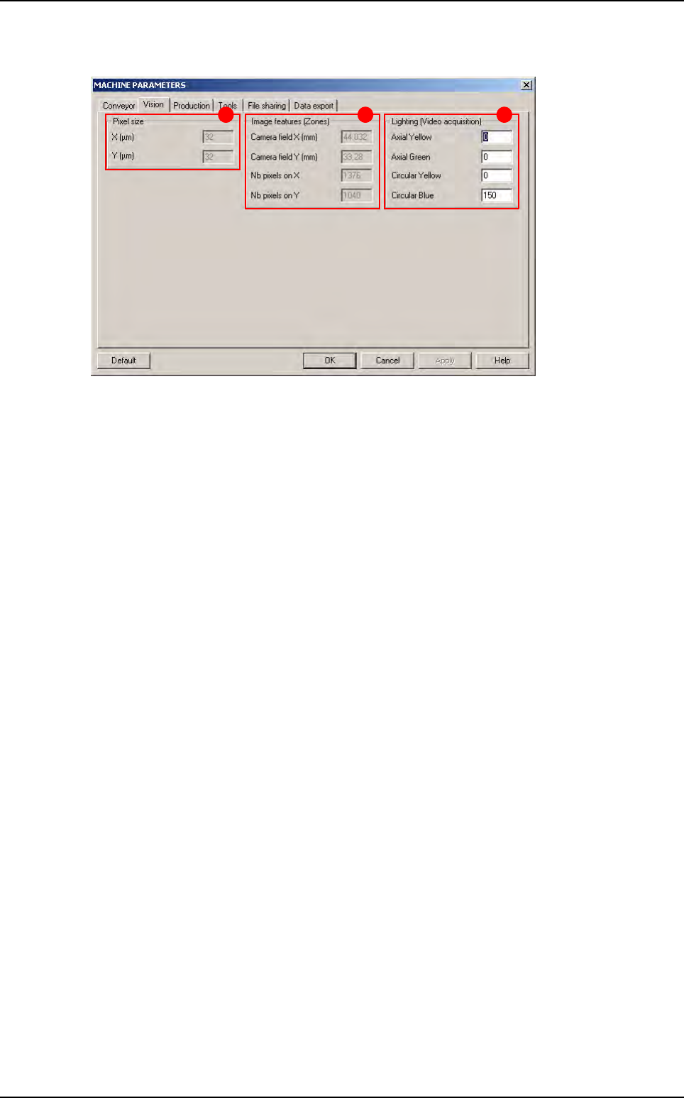
2.2.2 Vision tab
The Pixel size (A) is directly obtained when the AOI system is calibrated in the Test machine,
Calibration menu.
The
Image features (Zones)
(
B
) give the camera field of view. In the .tst files, the field of view
is called
Zone
.
Nb pixels …
gives the camera resolution (used to place the zones automatically).
Change the Lighting (Video acquisition) (C) parameters if you cannot see the image clearly
in the Cognex console when you move the camera with the AXIS mode in the MODE MAINTE-
NANCE.
B CA
Parameters
Maintenance mode
2 - 12 Vision 2007 4.10 User Manual Rev 01
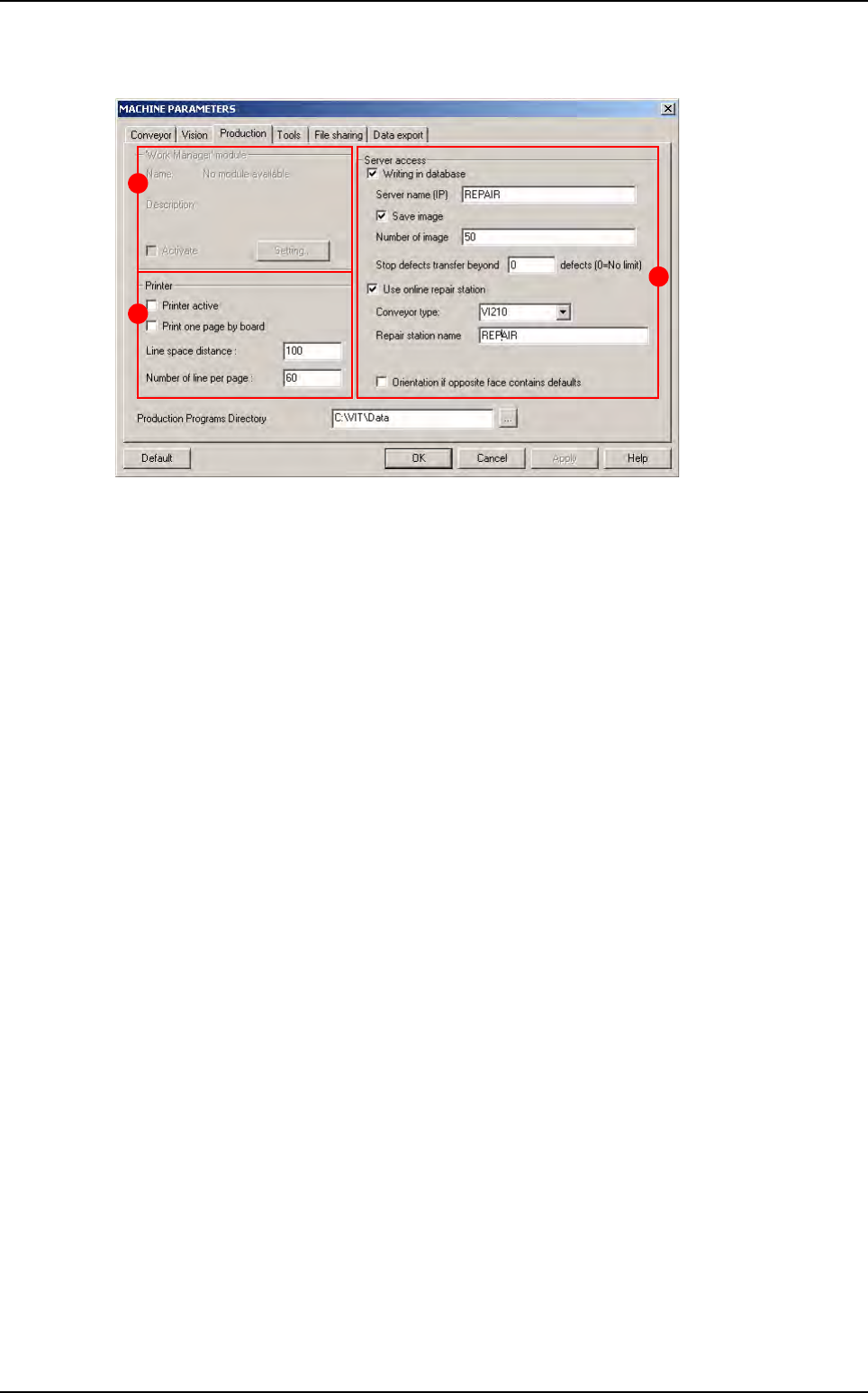
2.2.3 Production tab
In Work Manager module (A) (name by default when no module installed) section:
Tick Activate box to activate the customer extension module.
Click Setting... button to define the extension module.
In Printer (B) section:
Tick Printer active to connect the printer selected by default to the AOI system and thus
launch the printing of a list of faults detected by the machine during production.
Tick Print one page by board to obtain a paper print-out of each panel inspected during pro-
duction.
Line space distance: space between each line.
Number of line per page: number of line per page.
In Server access (C) section:
Tick Writing in database to save the inspection results in the supervision database:
• Server name (IP): name or IP address of the machine supervisor (use upper-case).
• Tick Save image to save images of the component defaults found in production, on the su-
pervisor computer.
• Number of image: number of images to transfer to repair station. It is also the number of
images for results table of the production screen (even if the number of images is less than
10 or if you do not active the Save image option, you will have 10 pictures in production).
• Stop defects transfer beyond ... defects: limit number of defects per panel to not transfer
the list of defects to the supervisor database.
Tick Use online repair station to repair the defaults online directly after inspection:
• Reparation name: name of the computer repair station (use upper-case).
• In Conveyor option:
- VI210: send good and bad boards on the same way.
- VI220 / VI210A: stop bad boards on the upper level waiting the operator reparation, while
good boards can carry on the production line.
- CO90B: direct bad boards on the repair station, while good boards can carry on the pro
duction line.
• Tick Orientation if opposite face contains faults to take into account the faults detected
by a previous AOI system when positioning the boards (in the case of a line with turning
over device for double-sided inspection).
A
B
C
Parameters
Maintenance mode
Vision 2007 4.10 User Manual Rev 01 2 - 13
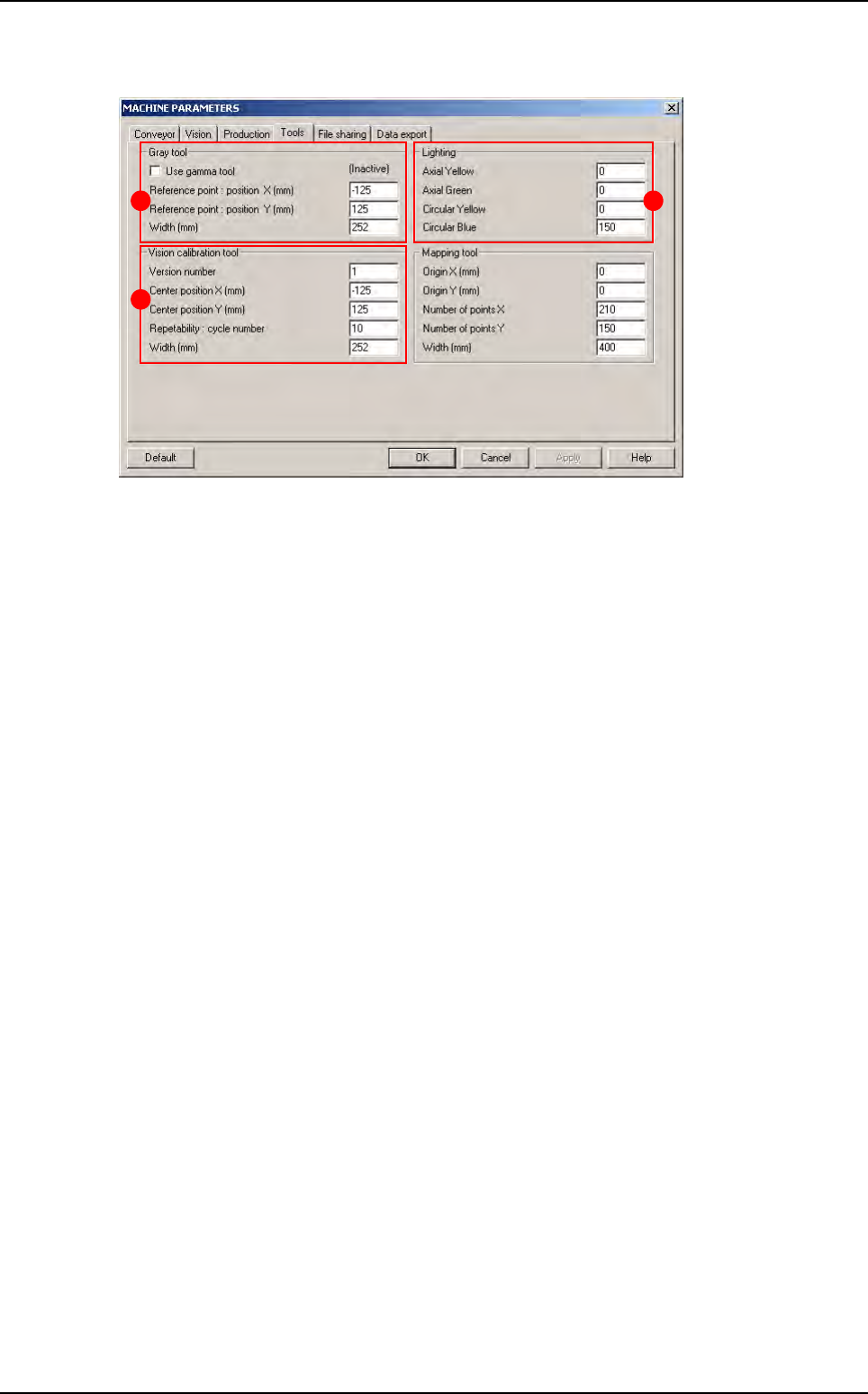
2.2.4 Tools tab
In Gray tool (A) section:
Tick Use gamma tool if a Vi-800G gray scale is used for the AOI system calibration.
Reference point: position XY (mm) correspond to the centre of the gray paper.
In Lighting (B) section is displayed the lighting used during definition adjustment and calibration
(by default 1 - 1 - 1 - 150).
In Vision calibration tool (C) section:
Version number correspond to the type of calibration tool (by default 1).
Center position XY (mm) correspond to the centre of vision calibration tool.
Repeatability is the number of measurement cycles run during repeatability of the AOI sys-
tem auto check.
A
C
B
Parameters