VI User Manual.pdf - 第64页
.VIS file 3 - 6 Vision 2007 4.10 User Manual Re v 01 3.1.3 Description in CAD reference 3.1.3.1 Panel fiducial and skip arrangement The panel fiducial s and skip definition is the same for the 3 different types of board …
.VIS file
Vision 2007 4.10 User Manual Rev 01 3 - 5
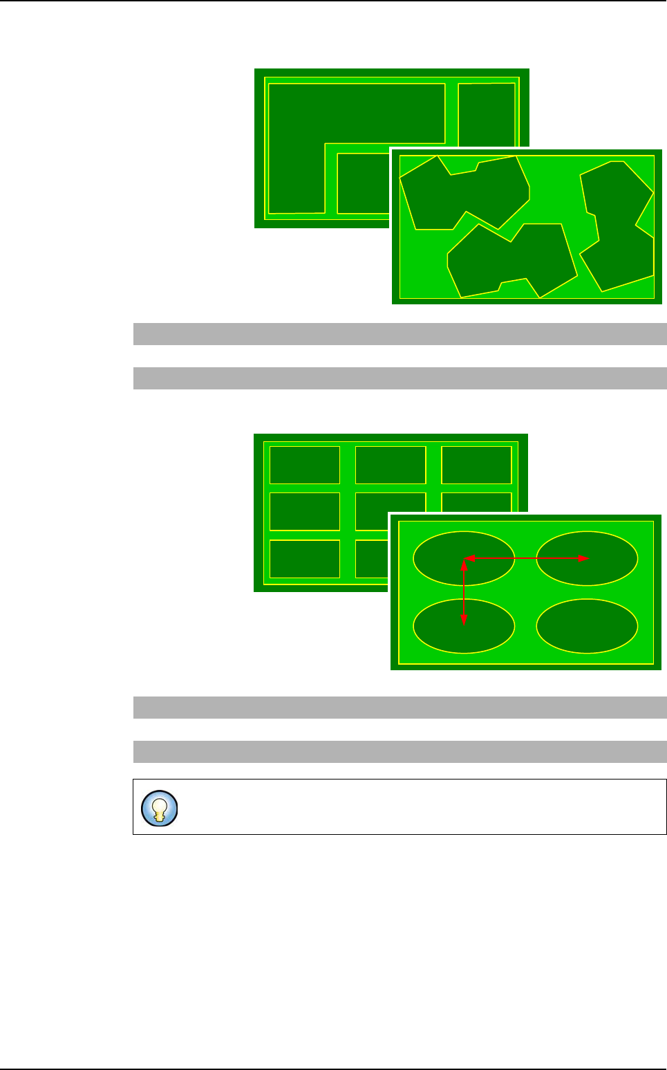
Step type
It is used to de-
scribe a panel of
boards with the
same shape and
different arrange-
ments.
Matrix type
It is used to de-
scribe a panel
of several iden-
tical boards
separated by a
constant step.
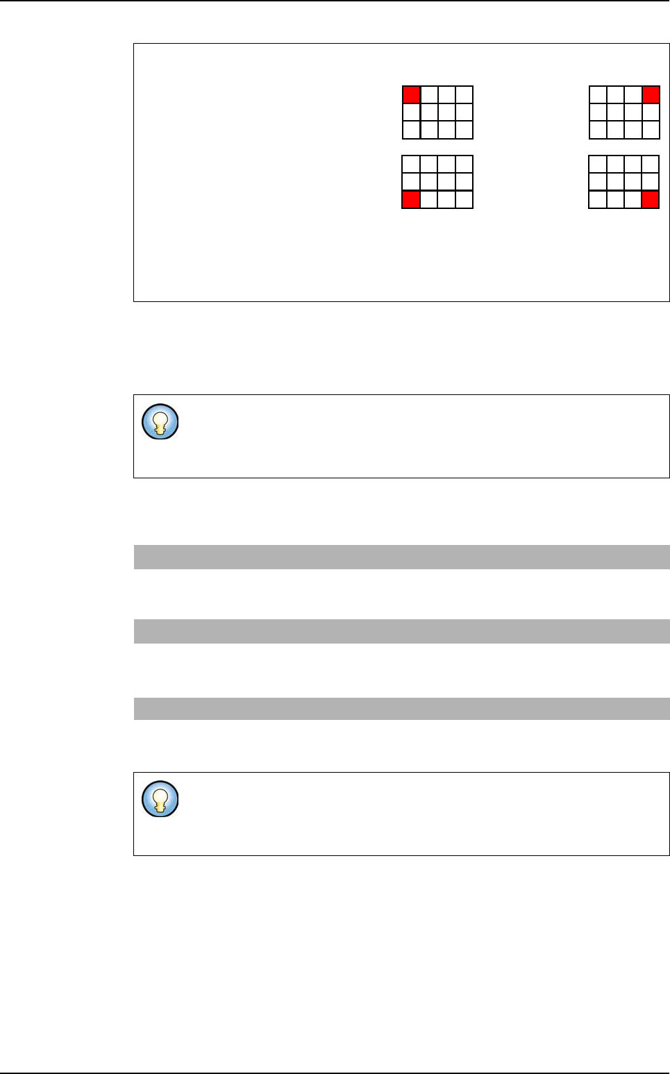
Rectangle STEP Dimx Dimy x1 y1
Θ
1x2 y2
Θ
2 … xn yn
Θ
n
Ellipse STEP Dimx Dimy x1 y1
Θ
1x2 y2
Θ
2 … xn yn
Θ
n
Polygon STEP x1 y1
Θ
1 x2 y2
Θ
2 … xn yn
Θ
n
Rectangle MATRIX Dimx Dimy Nbline Nbcol Stepx Stepy Order
Ellipse MATRIX Dimx Dimy Nbline Nbcol Stepx Stepy Order
Polygon STEP x1 y1
Θ
1 x2 y2
Θ
2 … xn yn
Θ
n
Step X, step Y: distance between 2 board centers.
Step X
Step Y
.VIS file description
.VIS file
3 - 6 Vision 2007 4.10 User Manual Rev 01
3.1.3 Description in CAD reference
3.1.3.1 Panel fiducial and skip arrangement
The panel fiducials and skip definition is the same for the 3 different types of board ar-
rangement.
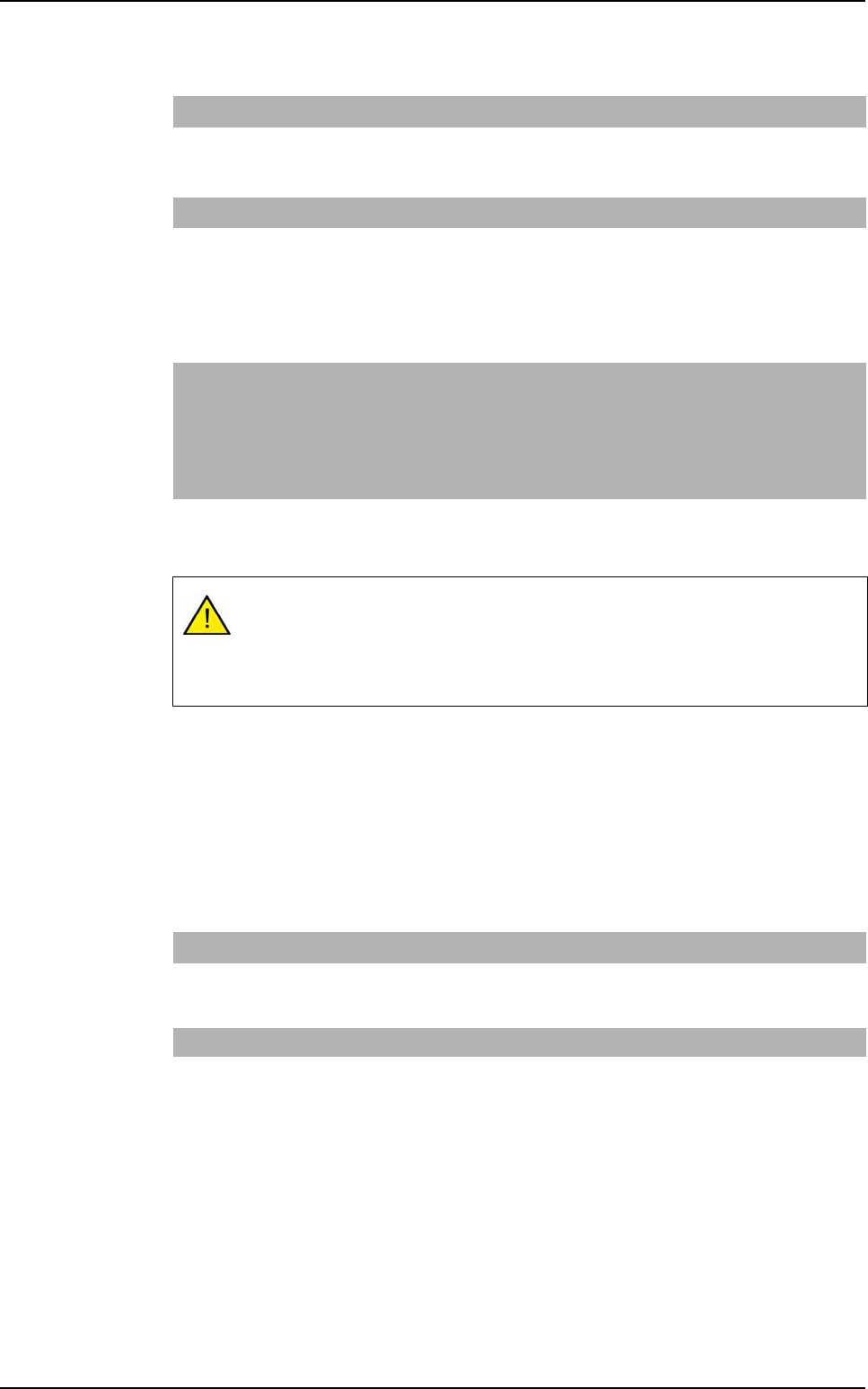
Matrix order
The two first letters give the
position of the first board:
L: Left,
R: Right,
T: Top,
B: Bottom
The third gives the scanning direction:
V: Vertical,
H: Horizontal
The fiducials used can be panel, board, or panel and board fiducials.
No limitation for fiducial number definition. But for inspection only 2 fiducials are
used.
Panel fiducials
FM n
i
, x
i
, y
i
Coordinates of panel
i
fiducial (number / position).
USED_FM
(optional)
n
1
, n
2
Number of the panel fiducials to be used. If this line is not
present, the first 2 panel fiducials declared are taken by
default.
Skip SKIP
b
i
, num
j
, x
j
, y
j
Coordinates of the num
j
skip of board
i
.
USED_SKIP
(optional)
b
i
, n Number of the skip to use for board b
i
. If this line is not
present, the first skip declared of board b
i
is taken by
default.
Data Matrix CB & Datamatrix
1D_2D_ Code
(optional)
X, Y,
Θ
Coordinates of the panel code
SKIP allows to mark the boards not to be inspected on the panel in the
production mode (not all the panel boards are OK).
You must declare as many skip as you have boards on the panel.
LT... RT...
LB... RB...
.VIS file description
.VIS file
Vision 2007 4.10 User Manual Rev 01 3 - 7
3.1.3.2 Board fiducials
This key word with 5, 6 or 7 symbols gives the component column order information.
The order is not important, however F and J can be empty, except if they are not at the
end of the line (in this case, they must contain at least a * (star)).
3.1.3.3 Component information
In the BOARD mode, the panel boards are all different. Therefore a component declara-
tion is required for each board (COMP i).
For this type, only declare coordinates for one board (they are the same for all boards).
BOARD type FMB
b
i
, num
j
, x
j
, y
j
Coordinates of the num
j
fiducial of board
i
.
USED_FMB
(optional)
b
i
, n
1
, n
2
Number of the board fiducials to use for board b
i
. If
this line is not present, the first 2 fiducials declared of
board b
i
are taken by default.
STEP & MATRIX type
FMB num
j
, x
j
, y
j
Coordinates of the num
j
fiducial of board
i
.
USED_FMB
(optional)
n
1
, n
2
Number of the board fiducials to use for board b
i
. If
this line is not present, the first 2 fiducials declared of
board b
i
are taken by default.
OBLIGATORY SYMBOLS T: topology
P: part number
X: X coordinate
Y: Y coordinate
A: angle
OPTIONALS SYMBOLS J: jedec
F: feeder
If CAD_IMP is not present, you must declare this order: X Y A P T, and you can
add field F.
If CAD_IMP is present, you can declare X Y A P T in any order and you can add
fields F and J.
Board COMP
i
Start of component coordinates declaration section of board
i
.
X, Y,
Θ
PART NUMBER
TOPO FEEDER
X and Y position, angle, part number, topology, name of machine placing
the component (optional). It is the default order when CAD_IMP is not
declared.
Step & Matrix COMP
Start of component coordinates declaration section of the reference board.
X, Y,
Θ
PART NUMBER
TOPO FEEDER
X and Y position, angle, part number, topology, name of machine placing
the component (optional). It is the default order when CAD_IMP is not
declared.
.VIS file description