VI User Manual.pdf - 第140页
Match Maker 6 - 6 Vision 2007 4.10 User Manu al Rev 01 6.3.1 Match Maker opening cond itions (Fiducial in spection) When clicking on the Match Maker button, the fiducials are execut ed with the defa ult settings. If the …
Match Maker
Vision 2007 4.10 User Manual Rev 01 6 - 5
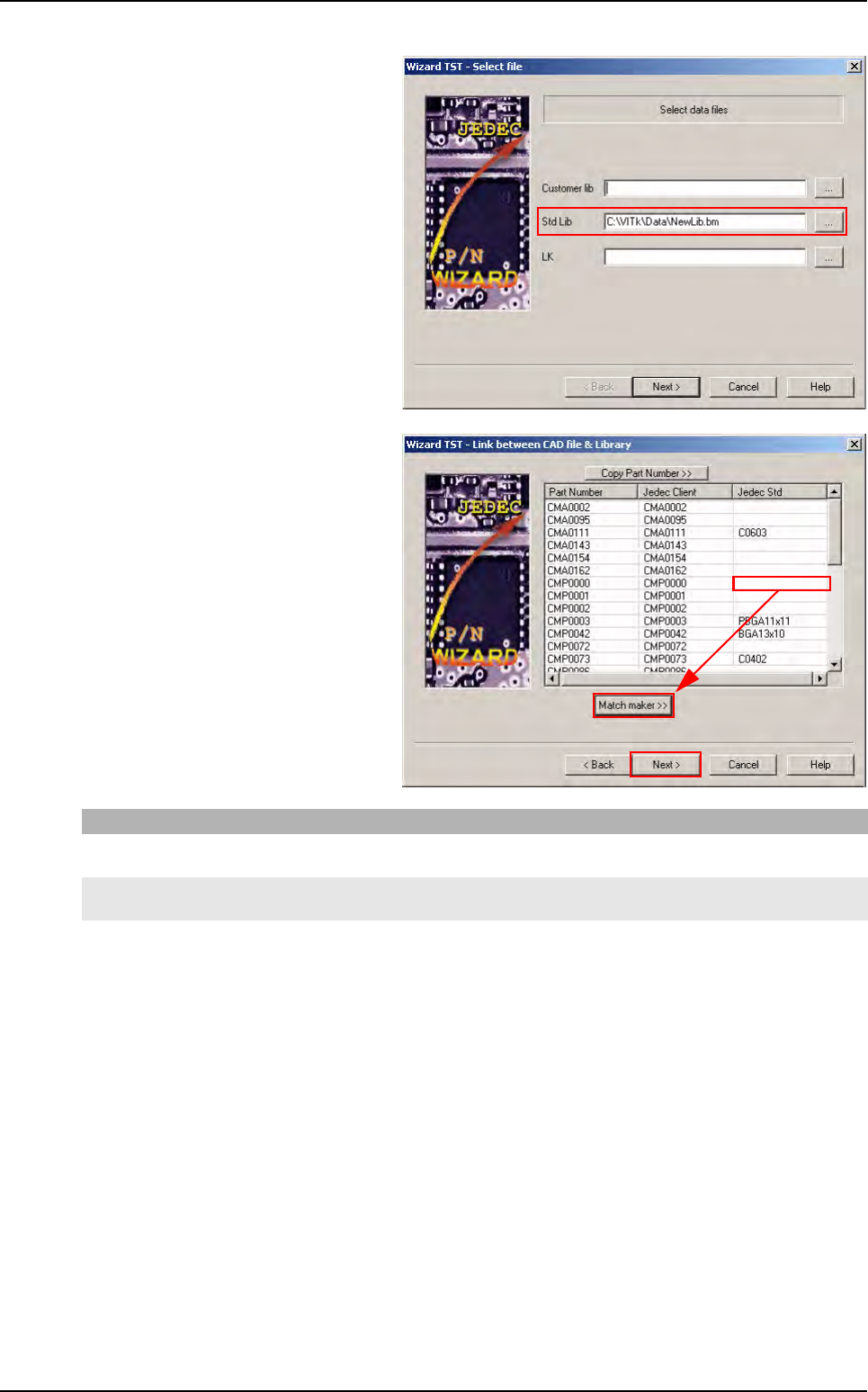
7. The Wizard TST - Select file window
appears.
This window indicates the Standard Li-
brary path, this value is defined in the
Match Maker configuration menu (if
not: see § 6.2 Configuration).
Click on the Next > button.
8.The Wizard TST - Link between CAD
file & library window appears.
At this step, if a Jedec Standard field
is empty, a Match maker >> button ap-
pears and it is possible to open the
Graphical User Interface (GUI).
If you click on Then
Match maker >>
button
The fiducials are inspected in order to correct the position of the board in the machine (see § 6.3.1
Match Maker opening conditions (Fiducial inspection)) then Match Maker opens.
Next > button The Wizard TST - Create missing treatments window opens (see § 6.5 Wizard TST after use of
Match Maker) and the user indicates the Part Number dimensions.
Match Maker in the Wizard TST
Match Maker
6 - 6 Vision 2007 4.10 User Manual Rev 01
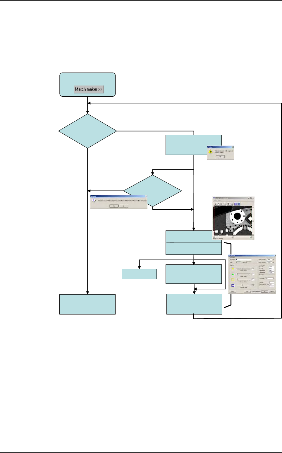
6.3.1 Match Maker opening conditions (Fiducial inspection)
When clicking on the Match Maker button, the fiducials are executed with the default settings.
If the execution of the fiducials fails, several windows appear.
6.3.1.1 Opening conditions diagram
Click on
Fiducials
execution
NOT OK
Adjustment
Edit Fiducial
Click on
button OK
OK
Click on
button YES
Click on
button NO
1st execution
Camera console
Edit Fiducial
2nd execution
Match Maker
Interface opens
Test
Warning screen
Click on
button OK
Open
Fiducial Edition ?
Match Maker in the Wizard TST
Match Maker
Vision 2007 4.10 User Manual Rev 01 6 - 7
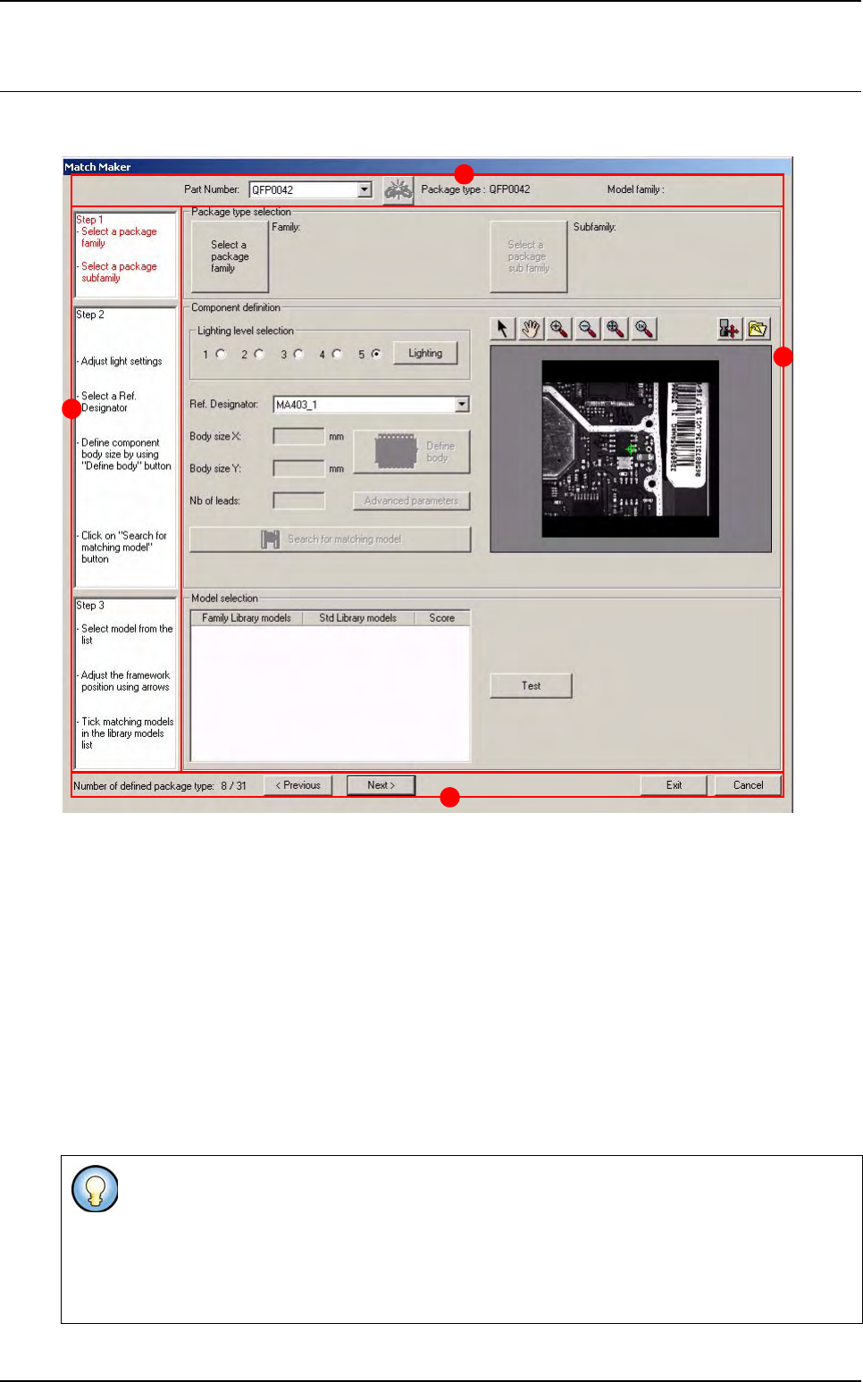
6.4 Match Maker graphical user interface
The Graphical User Interface (GUI) is organized in several steps in order to guide the user.
In the Top part of the window three informations and one button are displayed (A):
Part Number
«unlink» Part Number to Package type button
Package type
Model family.
On the left part a white bar contains the three steps (B) to be followed.
Step 1 Package type selection
Step 2 Component definition
Step 3 Model selection
Next to each step, a frame (C) enables to realize the actions.
In the Bottom part of the window one information and four buttons are displayed (D).
Each step contains several informations indicating the actions to realize. The status of the step
is defined with a color:
- Black: step on standby
- Red: step to be realized in first
- Green: step realized and validated
D
B
A
C