VI User Manual.pdf - 第127页
.TST file edition Vision 2007 4.10 User Manua l Rev 01 5 - 19 5.7.2.4 Pin naming tab This tab allows to renam e connector's pin. In Matrix type ( A ) section, the pins are named from 1 to th e number of pin in the c…
.TST file edition
5 - 18 Vision 2007 4.10 User Manual Rev 01
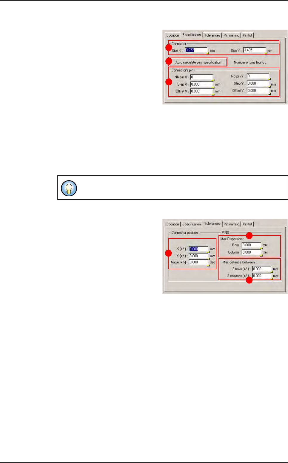
5.7.2.2 Specification tab
This tab shows the connector features.
In Connector (A) section, the Size X
& Y is the connector size in X, Y direc-
tion.
Press Auto calculate pins specifica-
tion (B) button to calculate automati-
cally connector feature according to
pin which are under the connector. If
you have not pin in your .tst file, you
can enter manually connector features
and the connector wizard could create pin component according to connector specifica-
tion.
In Connector’s pins (C) section:
Nb pin X & Y: number of pin in the connector in the X, Y direction.
Step X & Y: step, in X, Y direction, between 2 pins.
Offset X & Y: offset apply to the pin matrix from connector center position in X, Y direc-
tion.
5.7.2.3 Tolerance tab
This tab show the connector toleranc-
es and pin alignment tolerances
In Connector position (A) section:
X & Y (+/-): maximum distance be-
tween connector CAD and real posi-
tion in X, Y direction.
Angle (+/-): maximum angle between
connector CAD and real angle.
In Pins section:
Maximum dispersion (B):
Row: maximum distance between 2 pins of the same row in Y direction.
Column: maximum distance between 2 pins of the same column in X direction.
Maximum distance between (C):
2 rows (+/-): maximum distance between rows CAD and real step.
2 columns (+/-): maximum distance between columns CAD and real step.
All this specifications are given for a connector at 0°.
B
A
C
B
C
A
Connectors edition
.TST file edition
Vision 2007 4.10 User Manual Rev 01 5 - 19
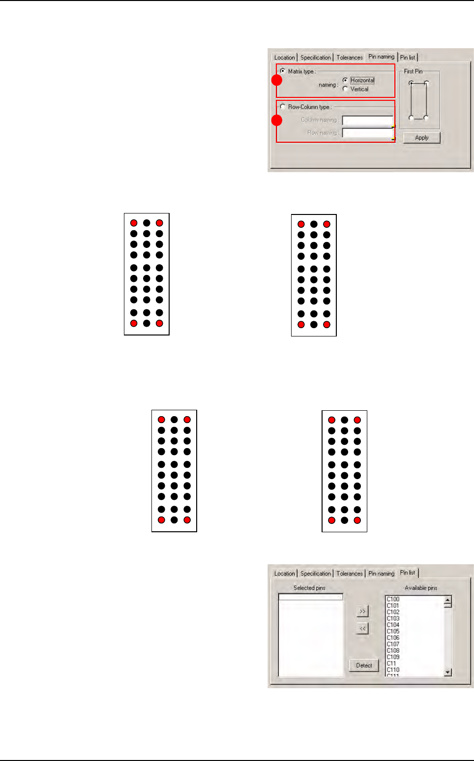
5.7.2.4 Pin naming tab
This tab allows to rename connector's
pin.
In Matrix type (A) section, the pins are
named from 1 to the number of pin in
the connector.
Horizontal way Vertical way
In Row-column type (B) section, you can choose column and row name.
Horizontal way Vertical way
5.7.2.5 Pin list tab
This tab shows you which pin are at-
tached to the connector. You can re-
move or add pin attachment as you
which but it is recommended to use
default attachment.
The Detect button lets you automati-
cally attach pin which are at the good
position under the connector.
A
B
Pin1
Pin2
7
Pin30
Pin3
27 30
1 3
Pin1
Pin10 Pin30
Pin21
10 30
1 21
Z A B
Pin Z_1
0
Pin B_10
Pin Z_1 Pin B_11
1
0
1 3
Pin3_10Pin1_1
0
Pin1_1 Pin 3_11
1
0
Connectors edition
.TST file edition
5 - 20 Vision 2007 4.10 User Manual Rev 01
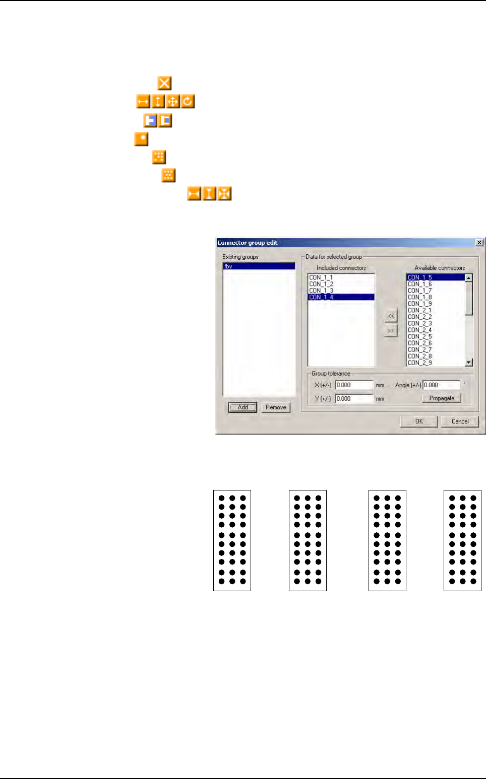
5.7.3 Connector result
Connector results are computed when all pins have been controlled. There are orange icon for
connector error:
Missing connector ,
Position error ,
Soldering error ,
Polarity error ,
Pin missing error ,
Pin alignment error ,
Column or line step error .
5.7.4 Connector group edition box
The connector group tool allows
to control alignment between
connector. This window shows
existing groups and their fea-
tures.
Thanks to the backplane inspec-
tion we can control components,
pin tip and pin through hole with
the same acquisition system.
5.7.5 Pin name
Currently, the pins are creat-
ing by importing a Gerber
file. Pins are linked to their
connector but they are
named in random way.
Z A B
27 30
1
10
1
1
0
10 30
1 3 1 21
Connectors edition