VI User Manual.pdf - 第356页
Reparation 14 - 4 Vi sion 2007 4.10 User Manual Rev 01 . In the Free keys ( A ) list, select one key and click on the button >> to add it to the used keys list. In the Used keys ( B ) list, select on e key and clic…
Reparation
Vision 2007 4.10 User Manual Rev 01 14 - 3
14.2 Reparation launching
14.2.1 First launching
The first time, the Reparation software is launched, a wizard is executed. It presents the fol-
lowing windows.
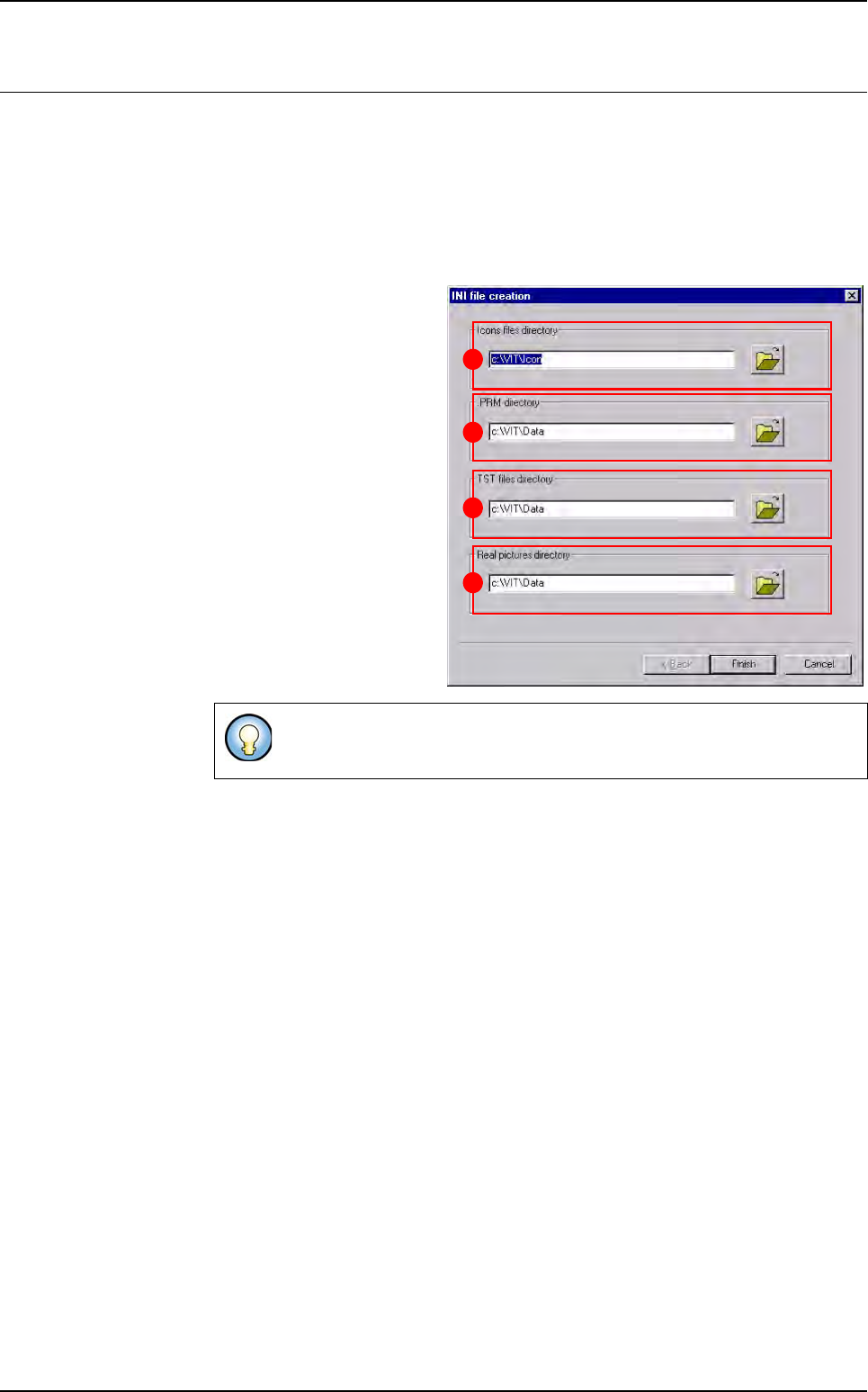
14.2.1.1 Path Setting window
This window lets you choose:
The Icons files directory
(A) where the software will
find the icons of each but-
ton.
The .PRM directory (B)
where the repair station
configuration file will be
saved.
The TST files directory (C)
where the software will find
the inspection program file.
The Real pictures directo-
ry (D) where the software
will find the images taken by
the AOI system, which show
the defects.
14.2.1.2 Main and detail buttons windows
These windows lets you configure the user interface and functionality of the 1st in-
terface showing the defects to repair. Clicking on one of the button from this inter-
face will set the same values to all the defects. To access to the detail of each defect
press F4 or the associated button.
The button list is totally configurable. You can:
Add and remove some buttons,
Change the text on the button,
Change the symbol on the button,
Change the function associated to the button,
Change the result information saved in the database.
To retrieve this window, go in Configuration menu and select Path set-
ting.
B
C
D
A
Reparation
14 - 4 Vision 2007 4.10 User Manual Rev 01
.
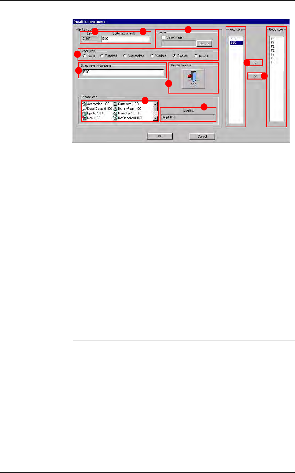
In the Free keys (A) list, select one key and click on the button >> to add it to the
used keys list.
In the Used keys (B) list, select one key and click on the button << to remove it and
let it free. All the used keys have defaults values and they also can be configured.
Click on one key from the Used keys list and set it as you want.
Selected key identification (C) of the keyboard.
In Button comment (D) field is displayed the button caption.
In Repair state (E) section, select the defect status associated to the button. It will
be saved into the database:
Not repaired: allow you to review the defect with the repair offline,
Invalid: all defects of the same board will have the Invalid status.
In String save in database (F) section, enter the comment associated to the but-
ton. It will be saved into the database.
In the list of predifined (G) icons, select the icon to associate to the selected key.
This list is in directory Icon and you can add you own files.
Preview (H) of the selected button.
File name ( I ) of the selected button.
In Image (J) section, you can associate the Save image function with some keys.
Select the folder in which you want the picture to be saved when the operator press
this button.
Main and Detail buttons windows differences
Even if the interfaces are the same, the keys list is different according to the se-
lected menu.
In the Main buttons menu the F4 key can not be removed from the used key list.
This button will always display the detail window. However, you can configure it
differently.
In the Detail buttons menu the F3 and F4 keys can not be removed from the
used key list. These buttons will always go to the next and the previous defect.
However, you can configure it differently.
To retrieve these windows, go in Configuration menu and select Main buttons
menu or Detail buttons menu.
A
B
C D
E
F
G
H
I
J
Reparation launching
Reparation
Vision 2007 4.10 User Manual Rev 01 14 - 5
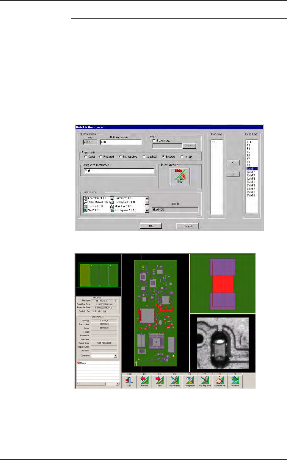
Two lines buttons option
You can add one row of buttons on the repair details screen.
1. Configuration
To configure this option, you have to change the following key on the Confi-
gReparation.ini file. Put 1 if you want two rows of buttons.
[Interface parameters]
Two lines of button=1
2. Details buttons menu
On the details buttons menu, you can now configure 18 buttons.You can con-
figure these like the buttons of the first line.
3. Repair details screen
Reparation launching