VI User Manual.pdf - 第46页
Maintenance mode 2 - 10 Vision 2007 4.10 User Manual Re v 01 2.2 Parameters 1. C lick PARAMETERS button in the MODE MAINTENANCE menu to bring up the MACHINE PA- RAMETERS window. 2. Click the tab to access the parameters …
Maintenance mode
Vision 2007 4.10 User Manual Rev 01 2 - 9
Calibration check (G).
Focus (H): check camera focus.
2.1.5 Open report
This function allows you to read the previous machine check reports found in C:/VIT/report.
2.1.6 Manual load
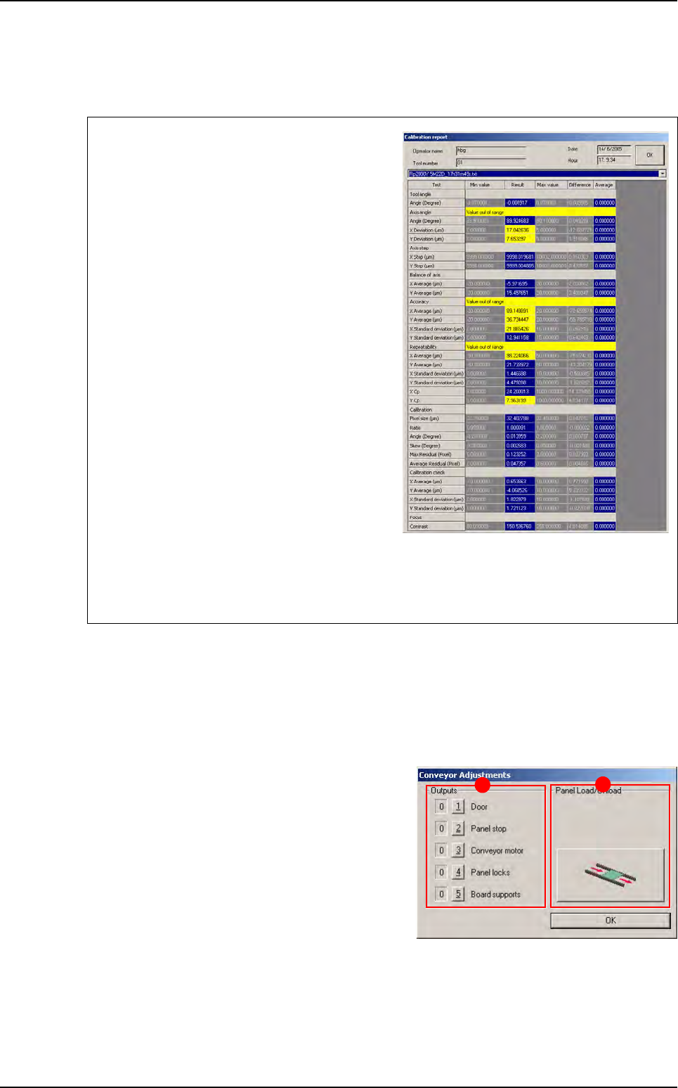
Outputs (A): each of the 5 buttons enables you to
activate one of the items listed.
Panel Load/uUnload (B): click on the Load/Un-
load button to automatically load and unload the
board.
Test failure is clearly marked in the report (yel-
low text fields for off-limit values and red text
fields for failed measurements, that are normally
due to unsuitable lighting or a dirty glass-plate).
The reasons for failed axes balance are:
Holding the camera in the wrong position.
Vibrations at lens level.
Incorrect fastening of the lens protective cover.
The reasons for failed accuracy are:
Wrong axis angle.
Wrong axis step.
The reasons for failed repeatability are:
Vibrations at camera level.
A dirty calibration tool.
If the calibration check fails, it means that calibration parameters in the memory do not match
the physical conditions of the camera. In this case, recalibrate the pixel size with the Calibra-
tion menu.
A
B
Test machine
Maintenance mode
2 - 10 Vision 2007 4.10 User Manual Rev 01
2.2 Parameters
1. Click PARAMETERS button in the MODE MAINTENANCE menu to bring up the MACHINE PA-
RAMETERS window.
2. Click the tab to access the parameters that you want to view or modify.
3. Click OK button to confirm the values entered by default or the changes made and return to the
MODE MAINTENANCE menu.
4. Click Cancel button to leave the current procedure or return to the MODE MAINTENANCE menu.
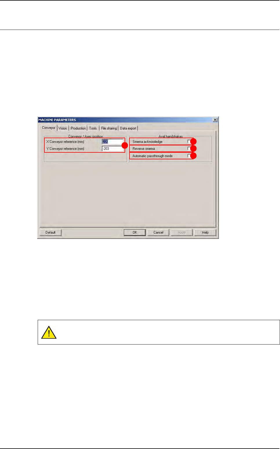
2.2.1 Conveyor tab
The XY conveyor references (A) are the distances between the axes 0 (position after initial-
ization) and the machine 0 (stop). If you change the position of the stop, these values must be
changed accordingly.
Tick Smema Acknowledge (B) to wait for acknowledgement of the downstream machine
(board received OK) in order to unload another board.
Tick Reverse Smema (C) to send the ready to send information to the downstream machine,
as soon as the output sensor is activated.
Tick Automatic passthrough mode (D) box to place the AOI system in the automatic
passthrough mode (by-pass).
If you have a fiducial or bar code error in production, the board will be sent to the down-
stream machine without any message.
A
B
C
D
Maintenance mode
Vision 2007 4.10 User Manual Rev 01 2 - 11
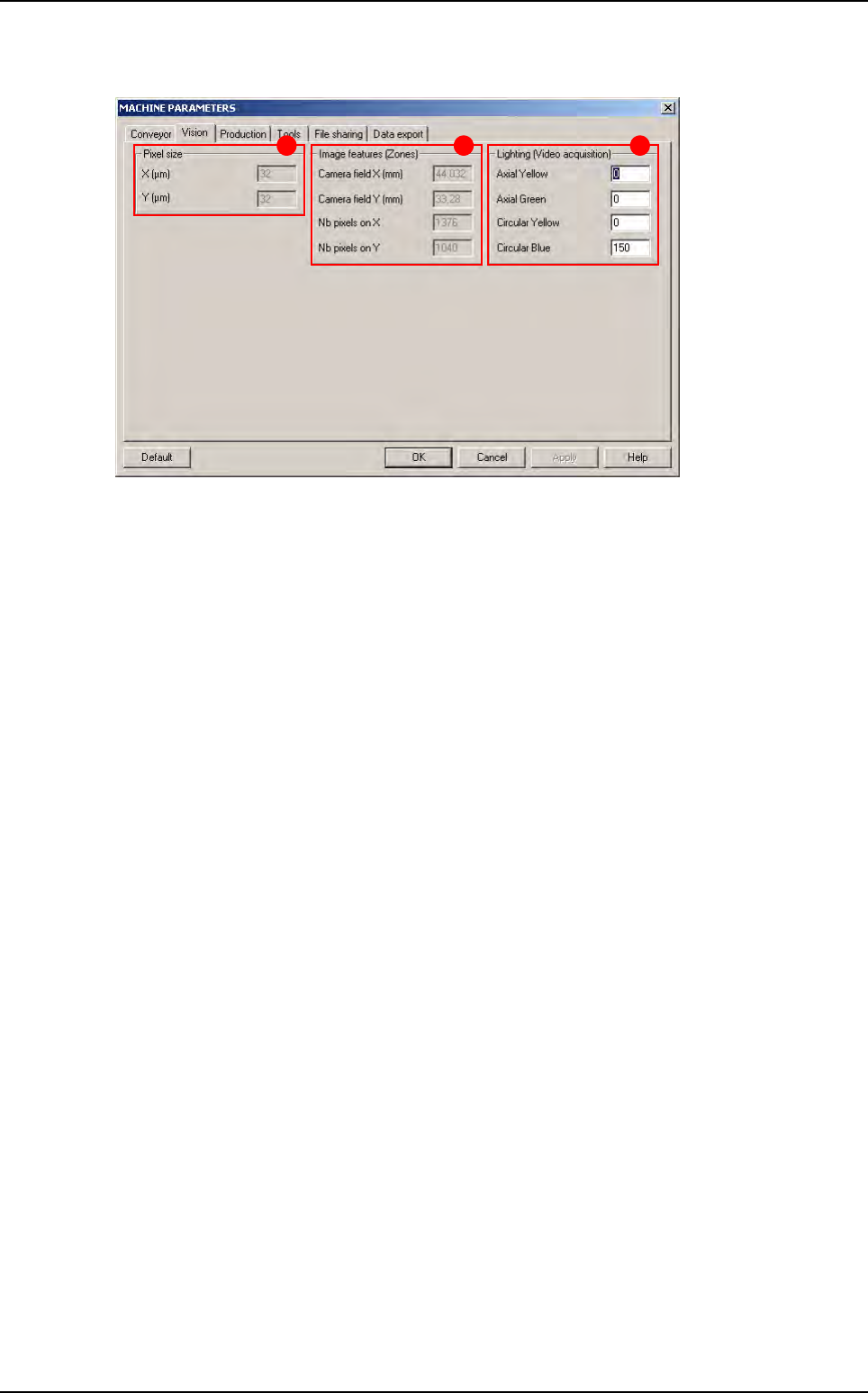
2.2.2 Vision tab
The Pixel size (A) is directly obtained when the AOI system is calibrated in the Test machine,
Calibration menu.
The
Image features (Zones)
(
B
) give the camera field of view. In the .tst files, the field of view
is called
Zone
.
Nb pixels …
gives the camera resolution (used to place the zones automatically).
Change the Lighting (Video acquisition) (C) parameters if you cannot see the image clearly
in the Cognex console when you move the camera with the AXIS mode in the MODE MAINTE-
NANCE.
B CA
Parameters