VI User Manual.pdf - 第294页
2D solder paste inspection 9 - 16 Vision 2007 4.10 User Manual Re v 01 9.8.3 Results 9.8.3.1 Paste inspection without flux algorithm The surface found is not the real so lder paste surface (only 55 %). Lighting level 1 (…
2D solder paste inspection
Vision 2007 4.10 User Manual Rev 01 9 - 15
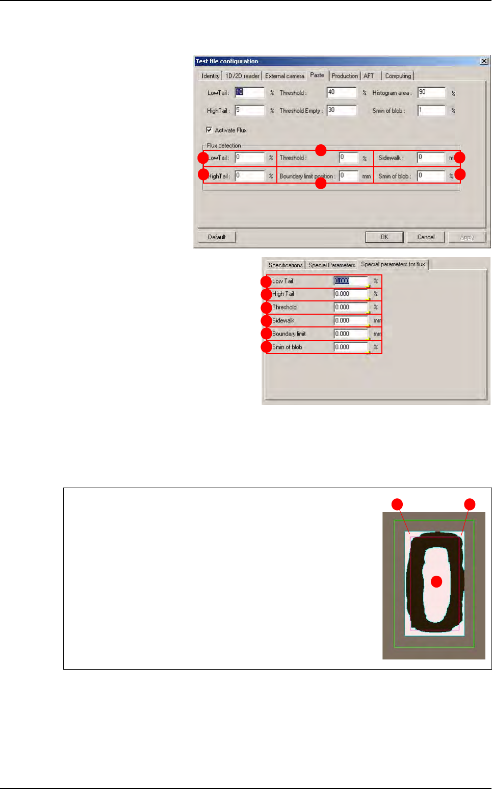
9.8.2 Flux detection parameters
You can find flux detection
parameters in the
Test file
configuration
window
(
Paste tab) or in the Edit
Pad
window (Special pa-
rameters for flux
tab).
The flux detection is done
by a blob tool which search
white shapes inside the
paste.
Low tail (A): lower limit (see § 9.3.3 Pro-
cessing parameters
).
High tail (B): upper limit (see § 9.3.3 Pro-
cessing parameters
).
Threshold (C): limit between paste and
flux (see §
9.3.3 Processing parame-
ters
).
Sidewalk (D): this length is added to the
theoretical pad size to create the blob
search area.
Boundary limit position (E): this length is
used to compute the boundary limit which exclude white shape from the blob result. This value
may be positive or negative.
Smin of blob (F): this limit is used to exclude white shape from the blob result if these shapes
are too small.
Green area is the search area of the blob (theoretical pad size + side-
walk).
Red area is the boundary limit (theoretical pad size + Boundary limit).
Blue areas are blob results. In this case 3 shapes are found by the
blob but only one (the
3rd) will be detected as flux.
Indeed, the
1st and 2nd shape are outside or touch the boundary lim-
it so they are rejected from flux detection.
Only the
3rd shape will be colored using the color define in the dya-
mant.ini file by the value indice coloriage (0,255) = 0.
This value must be set to the mean value of the paste.
B
C
D
E
F
A
A
B
C
D
E
F
3
1 2
Solder paste with flux algorithm
2D solder paste inspection
9 - 16 Vision 2007 4.10 User Manual Rev 01
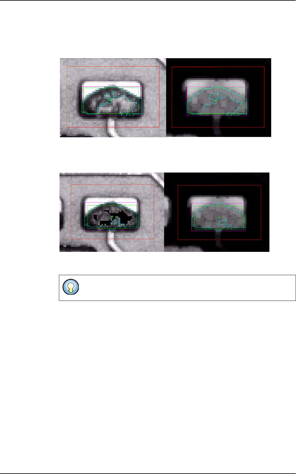
9.8.3 Results
9.8.3.1 Paste inspection without flux algorithm
The surface found is not the real solder paste surface (only 55 %).
Lighting level 1 (amber direct) Lighting level 2 (blue peripheral)
9.8.3.2 Paste inspection with flux algorithm
Lighting level 1 (amber direct) Lighting level 2 (blue peripheral)
The Flux algorithm option gives good result on fresh paste if there is lot of flux
in the solder paste, but this option increase the cycle time.
Solder paste with flux algorithm
Angle and distance calculation
Vision 2007 4.10 User Manual Rev 01 10 - 1
Chapter 10
Angle and distance calculation
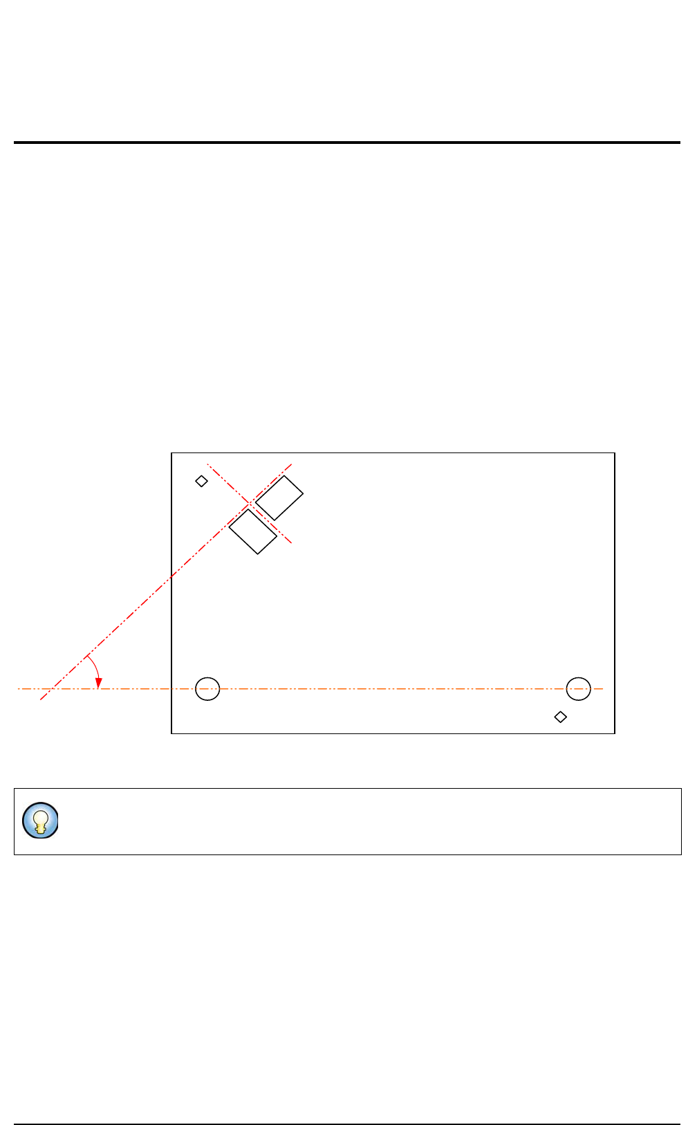
The Angle and distance calculation allows to verify that the distance and the angle measured between com-
ponents is within the tolerances.
You can check:
The distance in X direction between 2 components,
The distance in Y direction between 2 components,
The angle between 2 components,
The angle of a component when realigned with 2 others.
You define in a text file the distance and angle you want to measure. You specify the components reference
designators involved, the expected values and the tolerances.
If the text file is present the calculations are performed after the whole board inspection in Debug and in Pro-
duction mode as well.
Sensor 1 and sensor 2 must be at 90°.
Sensor 1 must be at 45° with the line made by 2 holes.
45° from
plane +/- .1
90° from the results
of Sensor 1
Fid 1
Sensor 1
Sensor 2
Mounting
hole 2
Mounting
hole 1
Fid 2
Plane (result from hole 1 and 2)