VI User Manual.pdf - 第183页
Tools library Vision 2007 4.10 User Manua l Rev 01 7 - 21 • The Tolerance (mm) ( G ) of the expected wid th between 2 transition s. Advanced parameters tab Filter half-size (mm) ( A ): filter size in microns. The sharper…
Tools library
7 - 20 Vision 2007 4.10 User Manual Rev 01
7.4.2 Edge tab
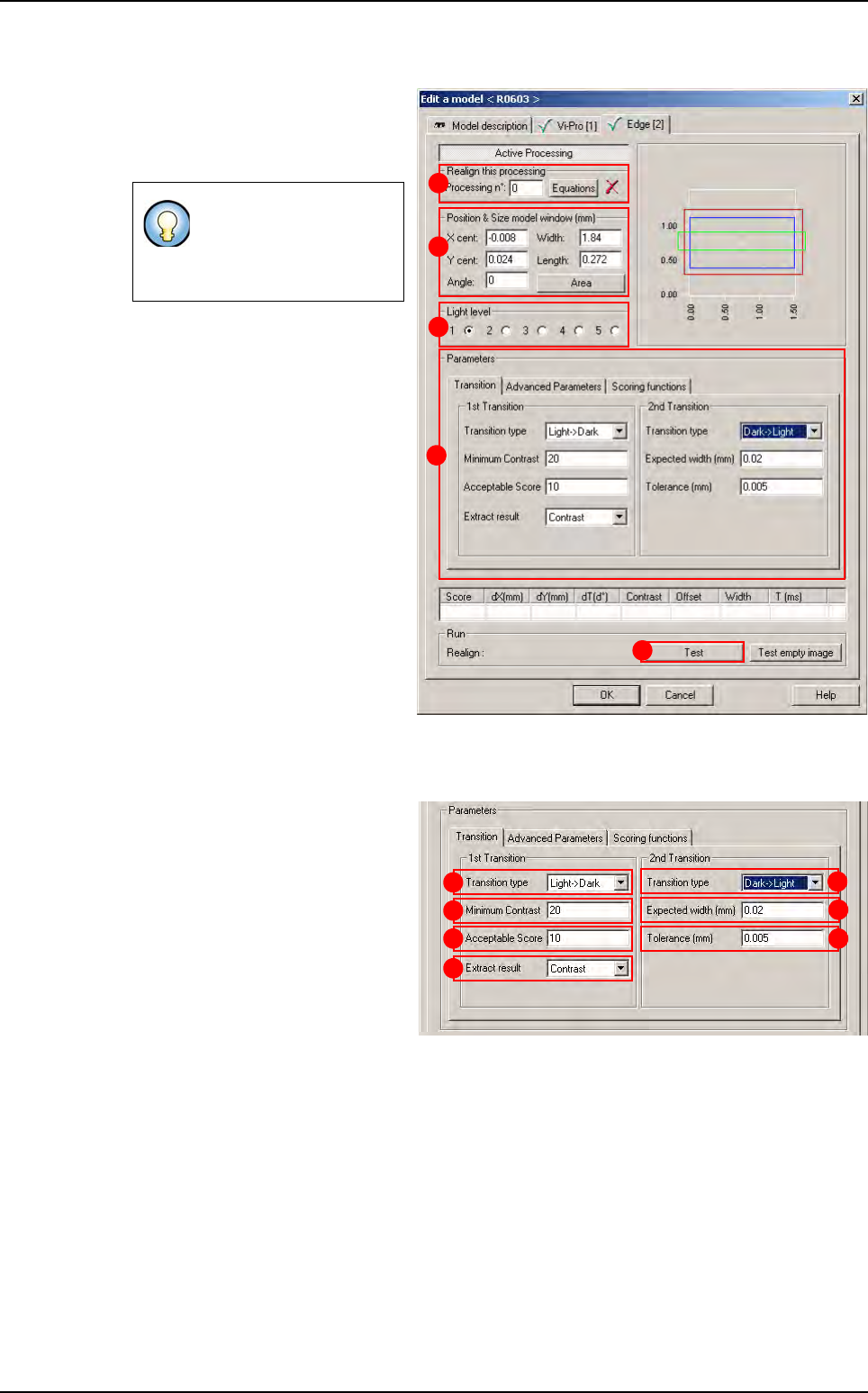
1.
Use
Realign this processing
(
A
)
section if you want to realign the po-
sition of the tool with another one
(not available for window 1)
.
2.
In
Position & Size model window
(mm)
(
B
) section, enter the size and
the position of the treatment win-
dow.
3.
In
Light level section
(
C
) section,
select the light level to use.
4. In Parameters (D) section, enter
the Edge tool parameters (see be-
low 7.4.2.1 Edge parameters).
5. Click Test (E) button to test the
Edge tool and display the results
(see below 7.4.2.2 Edge test).
7.4.2.1 Edge parameters
Transition tab
In 1st Transition, select for:
The Transition type (A)
searched.
The Minimum contrast (B)
threshold for edges.
The minimum Acceptable
score (C) for the result to be
considered OK.
The Extract result (D):
• Contrast: select contrast to specify the contrast scoring function. Use a contrast scor-
ing function to score edge based on edge contrast.
• Offset: extract the first transition.
• Size: you use a size scoring function to score edge pairs by comparing the edge pair
size to the edge pair width you specified in the expected width field.
In 2nd transition area:
• The Transition type (E) searched.
• The Expected width (mm) (F) between the 2 transitions.
If you need a special
equation to realign, you
can do so using the
Equations button.
B
C
A
D
E
A
B
C
D
E
F
G
Edge
Tools library
Vision 2007 4.10 User Manual Rev 01 7 - 21
• The Tolerance (mm) (G) of the expected width between 2 transitions.
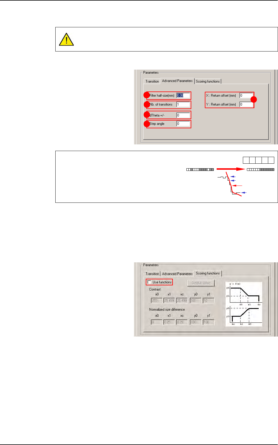
Advanced parameters tab
Filter half-size (mm)
(
A
): filter
size in microns. The sharper
the transition (short distance),
the smaller the filter, and vice
versa.
Nb of transitions
(
B
): defined number of objects that you are looking for in the treatment area.
XY: Return offset (mm) (C): X & Y offset position.
dTheta +/- (D): search angle of the treatment window.
Step angle (E): search angle step.
Scoring functions tab
Tick Use functions to adjust
Contrast and Normalized
size difference parameters
A zero value for Tolerance is not accepted and will generate many errors as
pixel size is different from
ε
0
.
The filter function enables you to:
• Regularize the gray levels and therefore avoid
detection of transitions due to image grain limit.
• Make a transition gradient.
A
B
D
E
C
-1 0
1
240
239
40
Filter result
1
-1
Edge
Tools library
7 - 22 Vision 2007 4.10 User Manual Rev 01
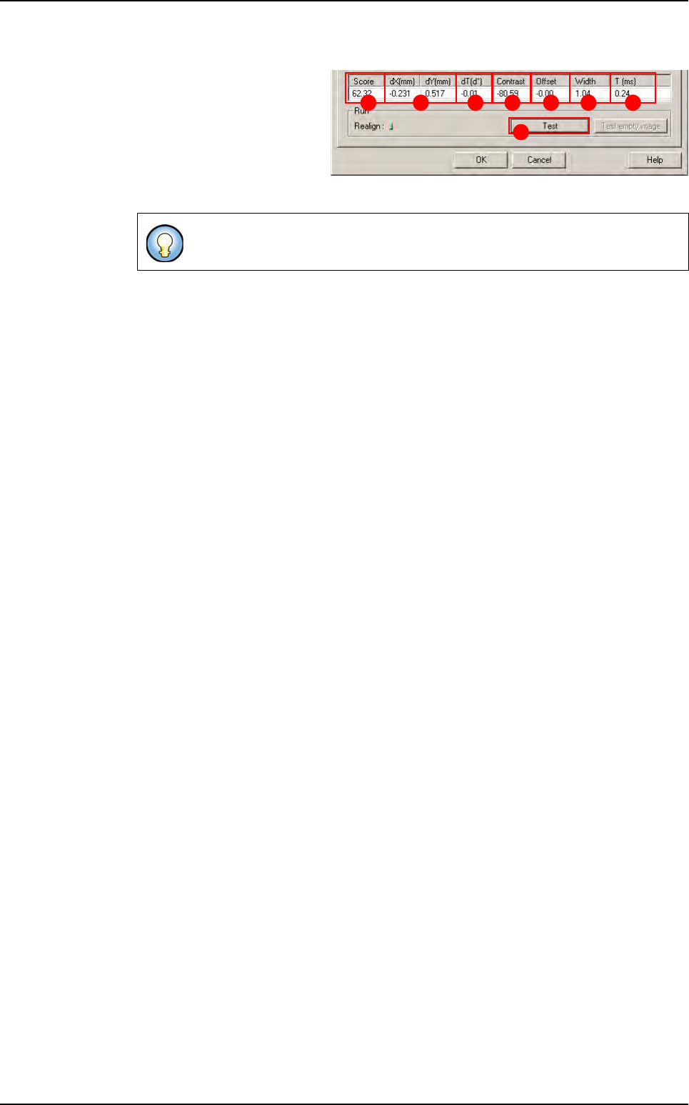
7.4.2.2 Edge test
Click on Test (A) button to
apply all the inspection pa-
rameters to the model.
Score (B): score of the test-
ed tool (rate of detection suc-
cess).
dXY(mm)
(
C
): position in X and Y between the transitions (center between the 2 transitions).
dT(d°) (D): position result in theta of the tested model.
Contrast (E): difference of a transition, in gray level values between background bright-
ness and component brightness. This value is the average of the transition contrast
found during the test.
Offset (F):
Width (G): width between the transitions found.
T (ms) (H): inspection time.
If only one transition is looked for, this is the position of the transition found.
A
B C D E F G H
Edge