VI User Manual.pdf - 第289页
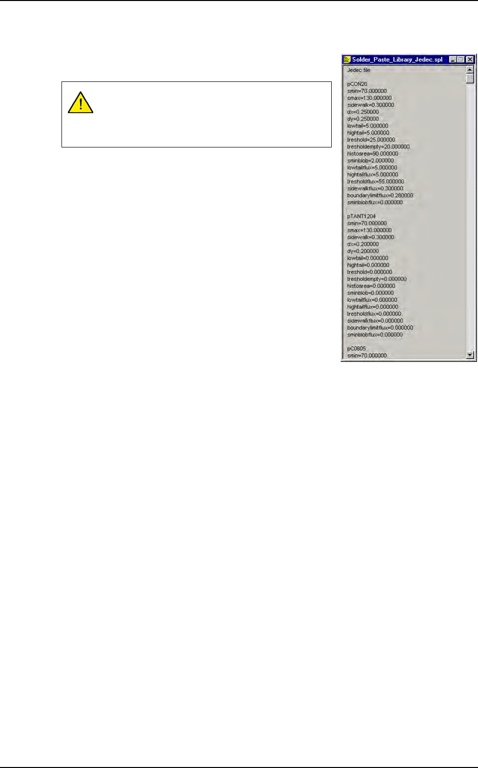
2D solder paste inspection Vision 2007 4.10 User Manua l Rev 01 9 - 11 9.5.2 .spl file based on JEDEC The first line must be jedec file otherwise Vision 2007 does not recognize that it is a .spl file based on JEDEC famil…
2D solder paste inspection
9 - 10 Vision 2007 4.10 User Manual Rev 01
9.5 .spl files
The .spl file is a Solder Paste Library. It is an ASCII file containing solder paste parameters which can
be imported into a .tst file.
Use .spl file if you need to set specific parameters to pads according to their geometrical properties or
according to their affected components.
To create a .spl file, go in Editor menu and select Open a text file. Choose the .spl file type. The text
editor window appears.
There are 2 files format. The first is based on pad geometry (length and surface) and the 2nd on
JEDEC.
9.5.1 .spl file based on pad geometry
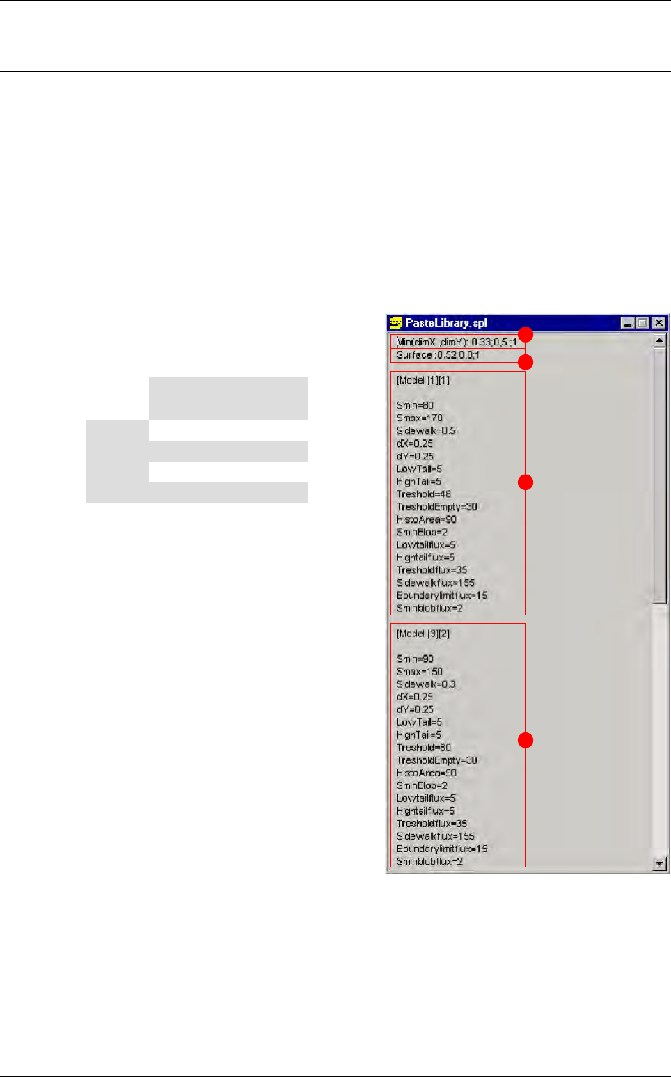
The 2 first lines create different geometrical sol-
der paste pad models (in this case 16 different
models).
A Min (dimX , dimY): 0.33; 0.5; 1 create differ-
ent classes based on the minimum pad size
(if dimX < dimY we take care of dimX and
vice-versa).
B Surface: 0.52; 0.8; 1 create different class
base on the pad surface.
C These parameters will be imported in solder
paste pads which have:
DimX or dimY < 0.33
Surface < 0.52
D These parameters will be imported in solder
paste pads which have:
0.5 < = dimX or dimY < 1
0.52 < = surface < 0.8
A
B
C
D
Surface
Min (dimX ; dimY)
< 0.33 < 0.5 < 1 > 1
< 0.52 [1][1] [2][1] [3][1] [4][1]
< 0.8 [1][2] [2][2] [3][2] [4][2]
< 1 [1][3] [2][3] [3][3] [4][3]
> 1 [1][4] [2][4] [3][4] [4][4]
2D solder paste inspection
Vision 2007 4.10 User Manual Rev 01 9 - 11
9.5.2 .spl file based on JEDEC
The first line must be jedec file otherwise Vision 2007 does not
recognize that it is a .spl file based on JEDEC family.
As for this .spl file format, when you import it into a .tst file, the
.spl file parameters are automatically entered in pads parame-
ters according to their JEDEC name.
9.5.3 .spl file importation
To import a .spl file, open the .tst file and in Test file menu go to Import and select Solder paste
file. The Open window appears. Select the .spl file you want to import.
In the .tst file, when you click on a paste pad, the imported .spl file parameters appear on the
Special parameters and Special parameters for flux tabs in the Pad edition window.
It is important to have linked pad to component (see
§ 9.2.2 Link pads to components) before importing
this kind of .spl file, otherwise all pads are pPaste JE-
DEC.
.spl files
2D solder paste inspection
9 - 12 Vision 2007 4.10 User Manual Rev 01
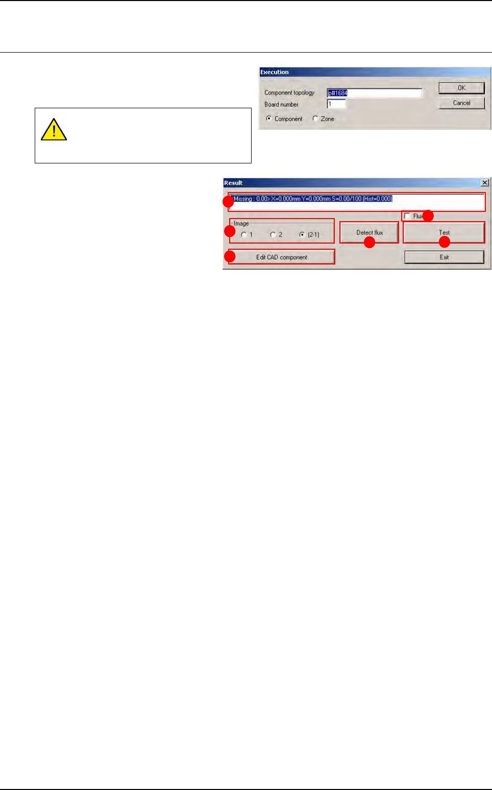
9.6 Paste pad execution (Ctrl + E)
The paste pad test is run as for normal
components. You can perform the same tests by
topology, JEDEC, zone, etc.
In Image (A) section select the lighting
level to display in the image window:
1 Lighting level 1 (amber direct).
2 Lighting level 2 (blue peripheral).
2 - 1 Subtraction of the 2 images.
Press Edit CAD component (B) button
to edit the paste pad and change certain
parameters.
The field (C) displays test results (∆x, ∆y, %S: theoretical surface area of the pad, histogram result).
The Flux (D) tick box enable or disable the flux algorithm during the solder paste control.
Press Detect flux (E) button to run the flux detection on the level 1. Shapes found are displayed in the
Cognex console and their position and surface are shown in the result window of the Ctrl + E box.
Press Test (F) button to re-test the paste pad.
Display of the paste pad must be acti-
vated in the .tst file for the paste inspec-
tion to be possible.
A
B
C
D
F
E