VI User Manual.pdf - 第162页
Match Maker 6 - 28 Vision 2007 4.10 User Manu al Rev 01 7. Launch Match Mak er . Clic k on the Match Ma ker button. The Match Mak er window appears: Select the same Part Number . 8. In the table, the family BGA15x15 appe…
Match Maker
Vision 2007 4.10 User Manual Rev 01 6 - 27
5. After having clicked on the Next button, continue in the Wizard TST such as (see § 6.5 Wiz-
ard TST after use of Match Maker).
In the Customer library there is the Standard Library model: CMA0162 which matched BGA
13x10.
6.6.3 New models to import in the Customer library
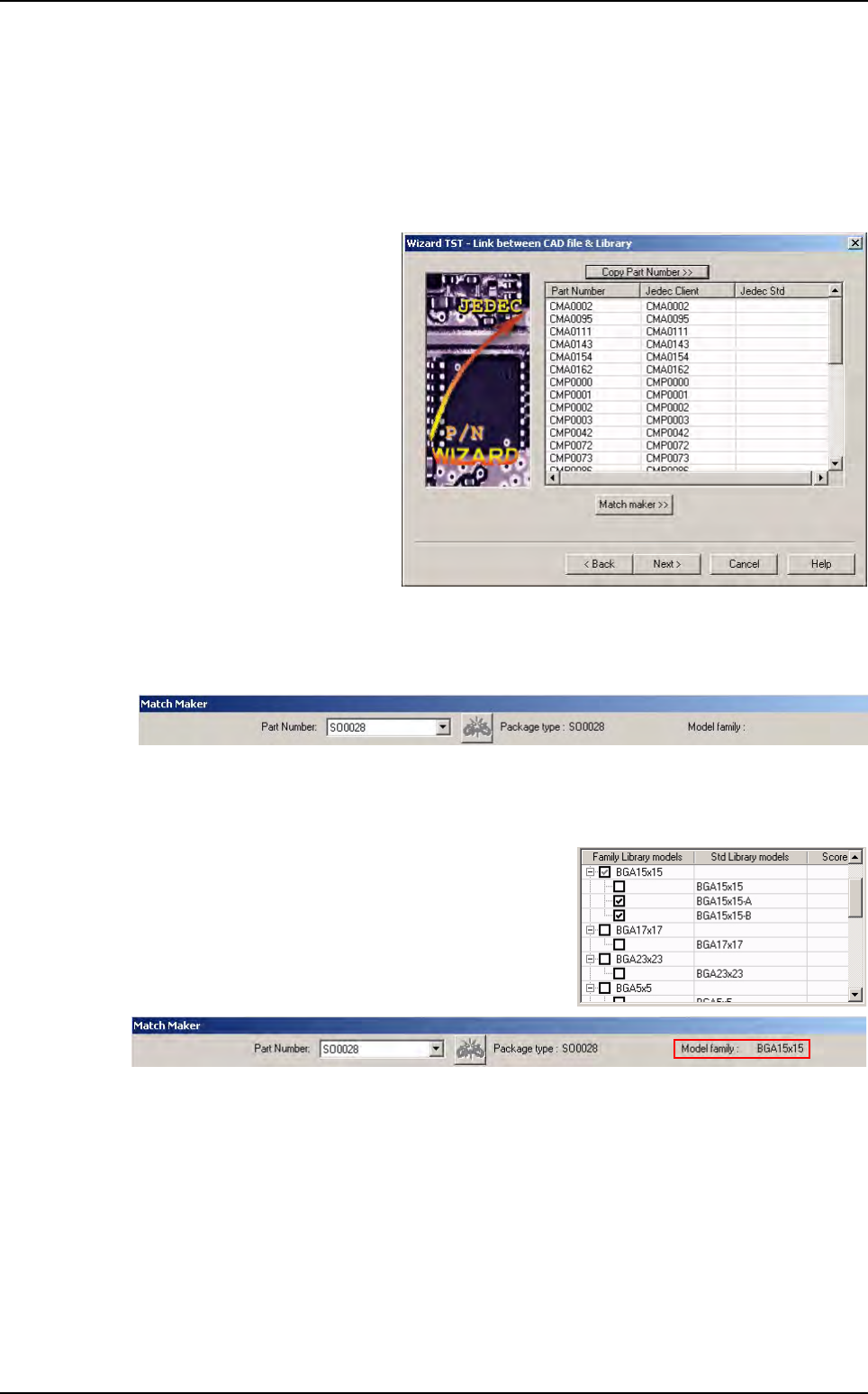
1. Run Wizard TST. The Wizard
TST - Link between CAD file
& Library window appears.
2. Launch Match Maker. Click on the Match Maker button. The Match Maker window appears:
Select a Part Number.
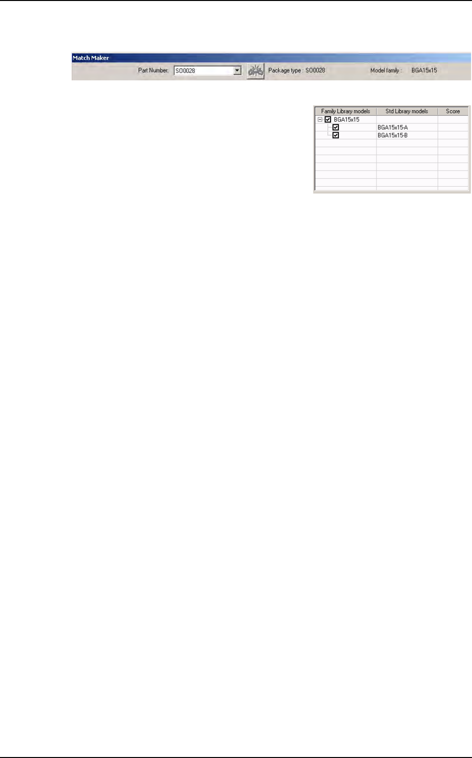
3. Associate a model of the Standard Library to a Part Number (see § 6.4.4 Step 3: Model
selection)
If the user ticks on BGA15x15-A and BGA15x15-B, the
family BGA15x15 is automatically ticked.
4. Leave Match Maker. Click on the Exit button. This family appears in the Wizard TST - Link
between CAD file & Library window.
5. After having clicked on Next button, continue in the Wizard TST such as (see § 6.5 Wizard
TST after use of Match Maker).
In the Customer library there are the Standard Library models:
BGA15x15-A
BGA15x15-B.
6. Run Wizard TST with a new VIS file containing the same Part Number.
Examples of link between Part Number and Library
Match Maker
6 - 28 Vision 2007 4.10 User Manual Rev 01
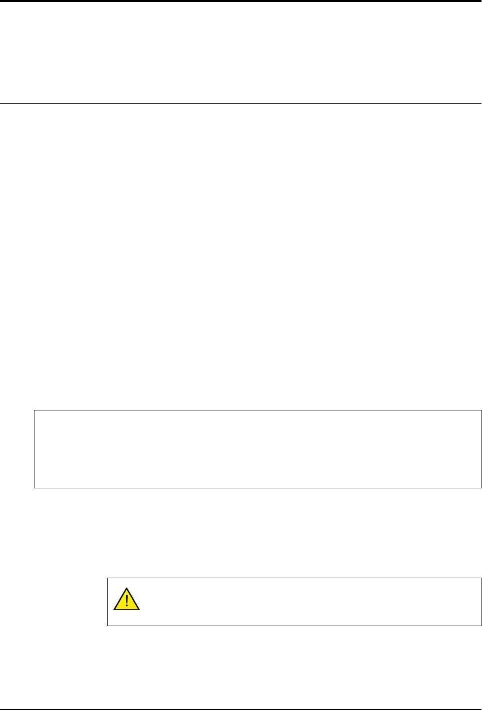
7. Launch Match Maker. Click on the Match Maker button. The Match Maker window appears:
Select the same Part Number.
8. In the table, the family BGA15x15 appears with the
models BGA15x15-A and BGA15x15-B.
9. After having clicked on the Next button, continue in the Wizard TST such as (see §6.5 Wizard
TST after use of Match Maker).
In the Customer library there are the Standard Library models:
BGA15x15
BGA15x15-A
BGA15x15-B.
Examples of link between Part Number and Library
Vision 2007 4.10 User Manual Rev 01 7 - 1
Chapter 7
Tools library
7.1 Component library
The component library is organized in 2 parts:
A .bm file containing information on the component models.
A directory of the same name containing the .cvl files.
The following information are general for each component model:
Component search window size.
Tolerances used for the inspection.
Tool(s) used for the inspection.
Link(s) between the different processing sequences.
Different lights used.
This chapter will teach you how to:
Create a table of images from a full and empty panel.
Create models in the library from the table of images.
Create synthetic images with BuildModel.
Create synthetic images with Image Edit.
7.1.1 Creating a table of images
7.1.1.1 Full panel
1. Run Vision 2007 software and open the .tst file corresponding to the panel that you
want to inspect. The conveyor will be adjusted automatically.
2. Click on the Load board icon or use the keyboard shortcut F3.
3. Click on the Fiducial execution icon to calculate panel readjustment. Check, and ad-
just if necessary, the intensity of the lighting.
To be able to use these different functions
You must have a .tst file corresponding to the panel that you want to inspect.
Fiducial treatment must be correctly defined to ensure proper board readjustment when the images of
the components are taken.
Place the panel with the components in the machine.
Ensure that the panel locks and board supports are properly adjusted.