VI User Manual.pdf - 第73页
.VIS file Vision 2007 4.10 User Manua l Rev 01 3 - 15 3.2.7 Components offset adjust window Change the G Offset coordinates ( A ) and press Ap ply G Offset t o preview button ( B ) to see the change directly in the viewe…
.VIS file
3 - 14 Vision 2007 4.10 User Manual Rev 01
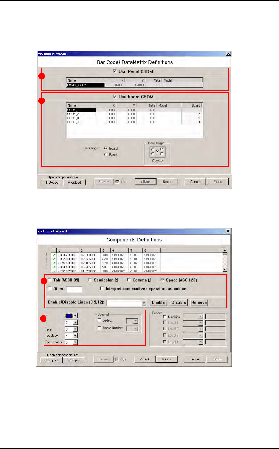
3.2.5 Bar code / Data Matrix definition window
In this window, tick Use panel CBDM (A) and/or Use board CBDM (B) in order to define bar
code/data matrix on the panel and/or on boards in .vis file.
3.2.6 Component definition window
This part of the wizard shows you the ASCII file you have selected in the first window.
The list show you the ASCII file. You can cross line in red just with one click on green sign or
double click on line.
The part A is used to define separator characters. List column are automatically refreshed if you
check or uncheck a character. You can also remove line from the list.
In the part B you must define where are the data in the list (which column for X, Y...).
A
B
A
B
.VIS file wizard
.VIS file
Vision 2007 4.10 User Manual Rev 01 3 - 15
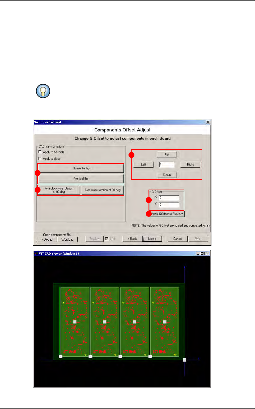
3.2.7 Components offset adjust window
Change the G Offset coordinates (A) and press Apply G Offset to preview button (B) to see
the change directly in the viewer. To adjust the G Offset more precisely, enter the wanted value
in the field (C), and click on Up and Right buttons to increase G Offset values or Down and Left
buttons to reduce it.
In CAD transformations area, click on Horizontal or Vertical flip buttons (D) to invert the po-
sition of components in the .vis file, and click on Anti-clockwise rotation of 90 deg or Clock-
wise rotation of 90 deg buttons (E) to rotate all components in the .vis file.
These transformations could also applied to fiducials and skip.
B
C
A
D
E
.VIS file wizard
.VIS file
3 - 16 Vision 2007 4.10 User Manual Rev 01
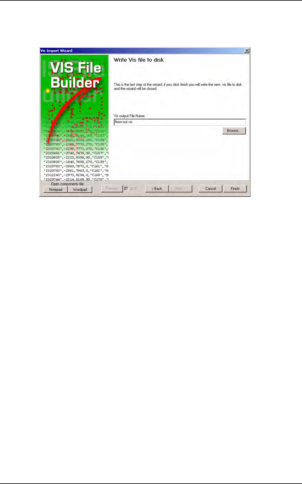
3.2.8 Write .vis file to disk window
The last window is to enter the file result name to be saved.
Click on Finish and the .vis file is automatically created.
.VIS file wizard