VI User Manual.pdf - 第287页
2D solder paste inspection Vision 2007 4.10 User Manua l Rev 01 9 - 9 9.4.2 Special parameters tab These parameters a re dedicated to this pad for solder pa ste de tection. When these parameters are set to 0 in this edit…
2D solder paste inspection
9 - 8 Vision 2007 4.10 User Manual Rev 01
9.4 Paste pad edition
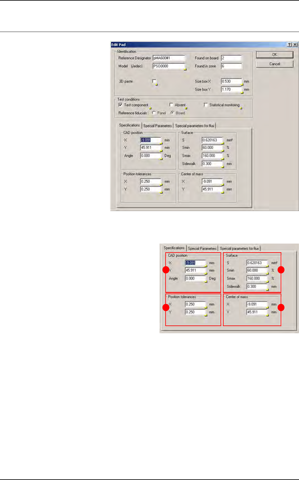
When you click on a paste pad
in the .tst file, the edition win-
dow below appears.
9.4.1 Specifications tab
In
CAD position
(
A
) section, enter the CAD
X and Y coordinates of the paste deposit.
In Position tolerances (B) section, enter
the acceptable tolerance of X and Y on the
position of the centre of gravity of the paste
deposit found (in 1/100th mm).
In Surface (C) section:
S
: theoretical surface area of paste deposit.
Smin & Smax: minimum and maximum ac-
ceptable surface area of paste.
Sidewalk: blob search area = theoretical
paste deposit area + sidewalk.
In Center of mass (D) section, enter the X and Y coordinates of center of gravity.
A
B
C
D
2D solder paste inspection
Vision 2007 4.10 User Manual Rev 01 9 - 9
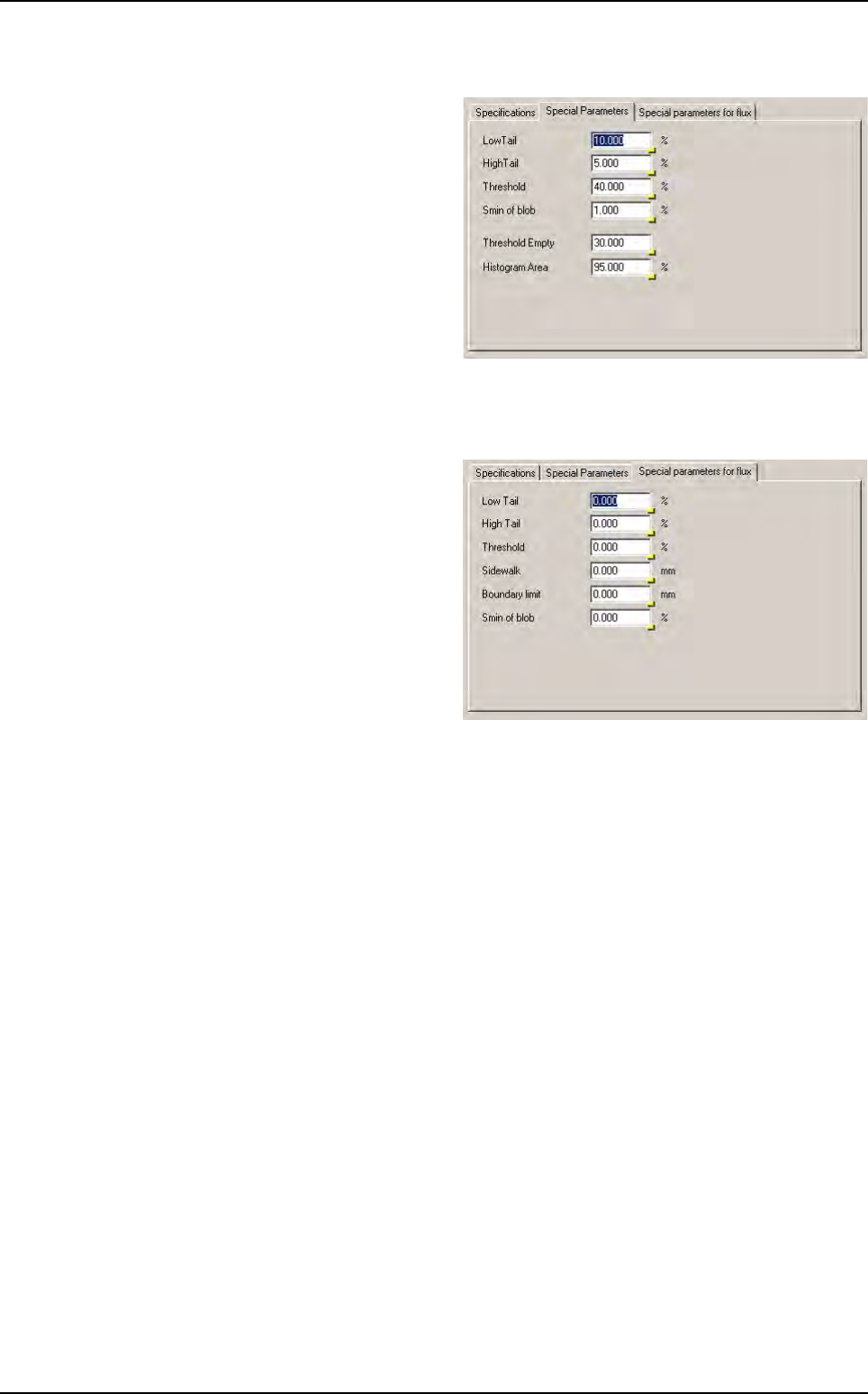
9.4.2 Special parameters tab
These parameters are dedicated to this
pad for solder paste detection. When these
parameters are set to 0 in this editing box,
the default parameters in the configuration
box of the .tst file are used for the inspec-
tion (see § 9.3.3 Processing parameters
for description).
9.4.3 Special parameters for flux tab
These parameters are dedicated to this
pad for flux detection. When these param-
eters are set to 0 in this editing box, the de-
fault parameters in the configuration box of
the .tst file are used for the inspection (see
§ 9.8.2 Flux detection parameters for de-
scription).
Paste pad edition
2D solder paste inspection
9 - 10 Vision 2007 4.10 User Manual Rev 01
9.5 .spl files
The .spl file is a Solder Paste Library. It is an ASCII file containing solder paste parameters which can
be imported into a .tst file.
Use .spl file if you need to set specific parameters to pads according to their geometrical properties or
according to their affected components.
To create a .spl file, go in Editor menu and select Open a text file. Choose the .spl file type. The text
editor window appears.
There are 2 files format. The first is based on pad geometry (length and surface) and the 2nd on
JEDEC.
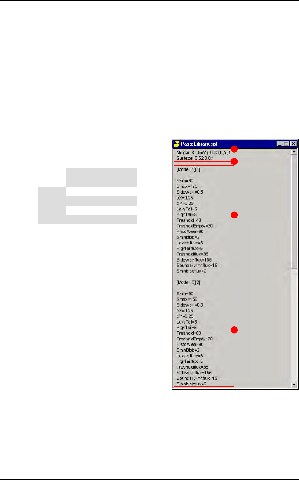
9.5.1 .spl file based on pad geometry
The 2 first lines create different geometrical sol-
der paste pad models (in this case 16 different
models).
A Min (dimX , dimY): 0.33; 0.5; 1 create differ-
ent classes based on the minimum pad size
(if dimX < dimY we take care of dimX and
vice-versa).
B Surface: 0.52; 0.8; 1 create different class
base on the pad surface.
C These parameters will be imported in solder
paste pads which have:
DimX or dimY < 0.33
Surface < 0.52
D These parameters will be imported in solder
paste pads which have:
0.5 < = dimX or dimY < 1
0.52 < = surface < 0.8
A
B
C
D
Surface
Min (dimX ; dimY)
< 0.33 < 0.5 < 1 > 1
< 0.52 [1][1] [2][1] [3][1] [4][1]
< 0.8 [1][2] [2][2] [3][2] [4][2]
< 1 [1][3] [2][3] [3][3] [4][3]
> 1 [1][4] [2][4] [3][4] [4][4]