VI User Manual.pdf - 第181页
Tools library Vision 2007 4.10 User Manua l Rev 01 7 - 19 7.4 Edge The Edge tool o perates by detection of grey level transitions. It is used to cal c ulate an X or Y position of a component or to check the po- larity of…

Tools library
7 - 18 Vision 2007 4.10 User Manual Rev 01
Recommendations for using Vi-Pro
Choose a representative synthetic model with clear lines
Delete unimportant lines and image noise.
Only train important lines.
A large model will be more accurate.
Search window size affects inspection time (width) x (length) x (search angle).
Reduction of the Fine grain limit parameters increases inspection time.
Increase of the Coarse grain limit parameters reduces inspection time.
Consideration of polarity slightly increases inspection time.
Set a Contrast Threshold greater than 0.0 to accelerate inspection.
Vi-Pro
Tools library
Vision 2007 4.10 User Manual Rev 01 7 - 19
7.4 Edge
The Edge tool operates by detection of grey
level transitions. It is used to calculate an X or
Y position of a component or to check the po-
larity of the components.
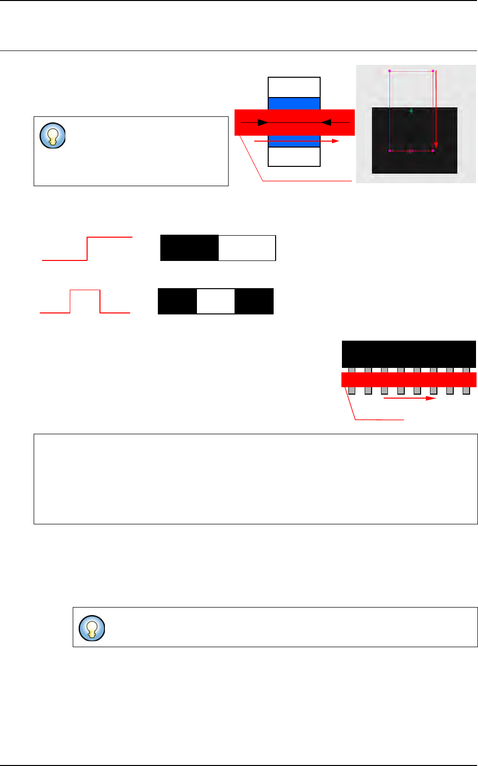
You can detect 1 or 2 transitions:
1 transition
2 transitions
Enables you to find a defined number of identical transitions within a
limited area.
Enables you to find the center of 2 distant transitions of a pre-defined
length.
7.4.1 Model description tab
1. On the Model description tab, in the Edit a model window, choose the treatment operation:
a new Edge tab appears behind the Model description tab.
2. Click Edit area button to define the component location in the image.
The Edge tool measures only 1 di-
rection.
Very accurate measurement tool (1/
10 pixel).
If the edge tool is used to find a defined distance between
2 transitions, tolerance must not be 0.
If you use synthetic model you can use
Auto area button.
Detection area and direction
Component
Width
Detection
direction
0
255
0
255
0
255
0
00
255
Treatment direction
Treatment area
1
st
2
nd
N
th
Tools library
7 - 20 Vision 2007 4.10 User Manual Rev 01
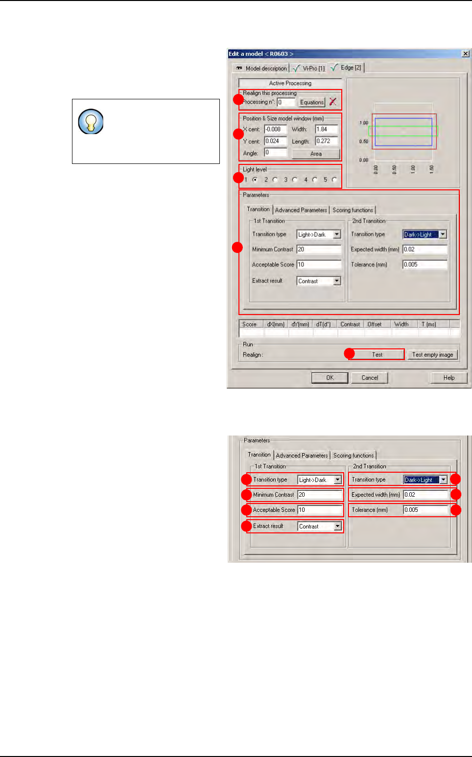
7.4.2 Edge tab
1.
Use
Realign this processing
(
A
)
section if you want to realign the po-
sition of the tool with another one
(not available for window 1)
.
2.
In
Position & Size model window
(mm)
(
B
) section, enter the size and
the position of the treatment win-
dow.
3.
In
Light level section
(
C
) section,
select the light level to use.
4. In Parameters (D) section, enter
the Edge tool parameters (see be-
low 7.4.2.1 Edge parameters).
5. Click Test (E) button to test the
Edge tool and display the results
(see below 7.4.2.2 Edge test).
7.4.2.1 Edge parameters
Transition tab
In 1st Transition, select for:
The Transition type (A)
searched.
The Minimum contrast (B)
threshold for edges.
The minimum Acceptable
score (C) for the result to be
considered OK.
The Extract result (D):
• Contrast: select contrast to specify the contrast scoring function. Use a contrast scor-
ing function to score edge based on edge contrast.
• Offset: extract the first transition.
• Size: you use a size scoring function to score edge pairs by comparing the edge pair
size to the edge pair width you specified in the expected width field.
In 2nd transition area:
• The Transition type (E) searched.
• The Expected width (mm) (F) between the 2 transitions.
If you need a special
equation to realign, you
can do so using the
Equations button.
B
C
A
D
E
A
B
C
D
E
F
G
Edge