VI User Manual.pdf - 第298页
Angle and distance calculation 10 - 4 Vision 2007 4.10 User Manual Rev 01 10.2.3 Macro to check the a ngle of 1 component and 1 line Topo1 and Topo2 will determine the straig ht line, and the macro ANGLE_STRAIGHTLINE_TOP…
Angle and distance calculation
Vision 2007 4.10 User Manual Rev 01 10 - 3
10.2 Macros definition
10.2.1 Macro to check the distance between 2 components
DISTANCE_X: function to calculate the distance in X direction
ALIGNEMENT_X = X
TOPO1
-X
TOPO2
DISTANCE_Y: function to calculate the distance in Y direction
ALIGNEMENT_Y = Y
TOPO1
-Y
TOPO2
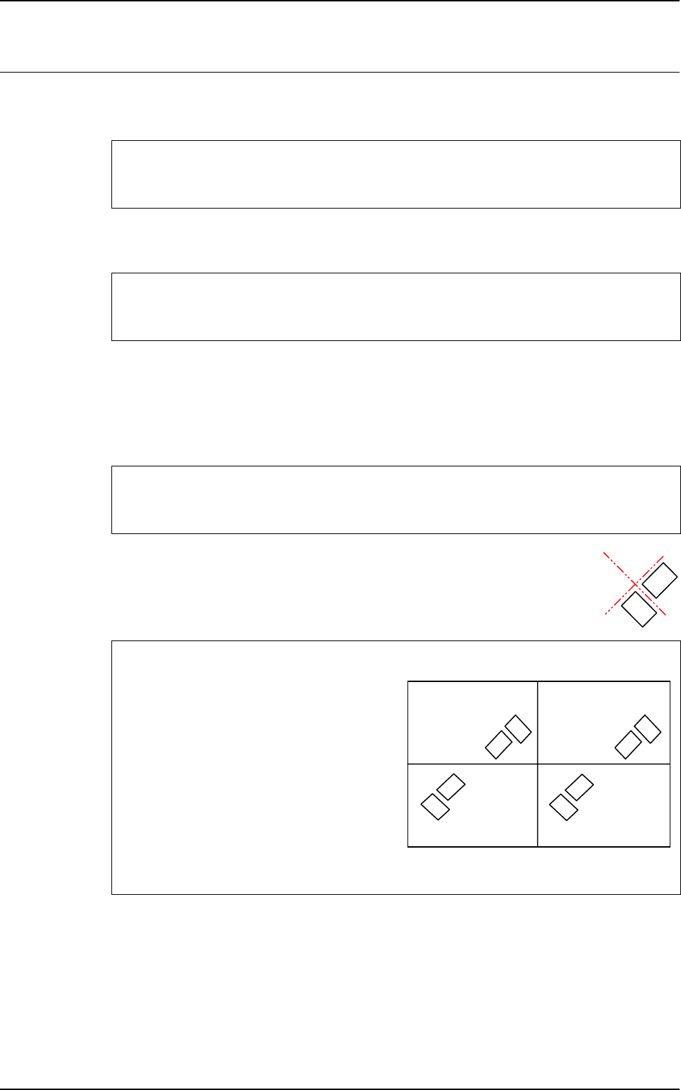
10.2.2 Macro to check the angle between 2 components
ANGLE_2_TOPO = T
TOPO1
-T
TOPO2
If <board number> = 0 we execute the function on all the boards of the panel.
The minimum and maximum tolerances can be asynchronous. (i.e.: - 0.100
and + 0.150).
DISTANCE_X <board number>
<result name> <TOPO1> <TOPO2> <expected value > <tolerance min> <tolerance max>
DISTANCE_Y <board number>
<result name> <TOPO1> <TOPO2> <expected value > <tolerance min> <tolerance max>
ANGLE_2_TOPO <board number>
<result name> <TOPO1> <TOPO2> <expected value > <tolerance min> <tolerance max>
To know the expected value to enter in the .mod file
<expected value > = T
TOPO1
-T
TOPO2
In the .tst file:
• Board 1 & 3: T1 = 315° T2 = 45°
⇒
T1-T2 = 270°
• Board 2 & 4: T1 = 135° T2 = 225°
⇒
T1-T2 = - 90°
In the .mod file:
• ANGLE_2_TOPO 0
• SENSOR-ANGLE T1 T2 270 0.1 0.1
Board 1
at 0°
Board 3
at 0°
Board 2
at 180°
Board 4
at 180°
Topo1
Topo2
Topo1
Topo2
Topo1
Topo2
Topo1
Topo2
Angle and distance calculation
10 - 4 Vision 2007 4.10 User Manual Rev 01
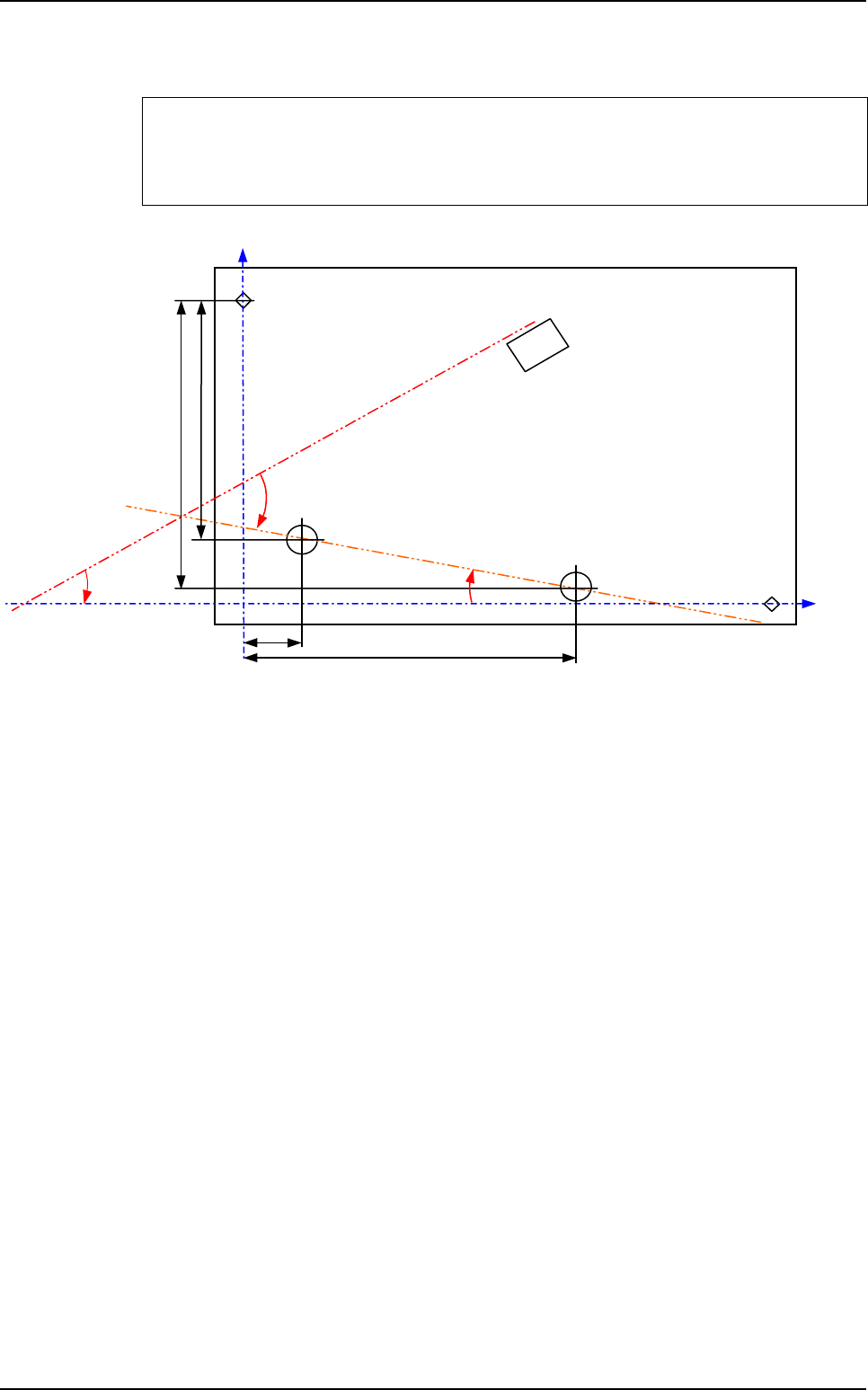
10.2.3 Macro to check the angle of 1 component and 1 line
Topo1 and Topo2 will determine the straight line, and the macro
ANGLE_STRAIGHTLINE_TOPO will return the angle between this line and Topo3.
ANGLE_STRAIGHTLINE_TOPO <board number>
<result name > <TOPO1> <TOPO2> <TOPO3> <expected value > <tolerance min>
<tolerance max>
ρ
T
Topo3
θ ?
Fid 1
Topo2
Topo1
Fid 2
Y1
Y2
X2
X1
Macros definition
Angle and distance calculation
Vision 2007 4.10 User Manual Rev 01 10 - 5
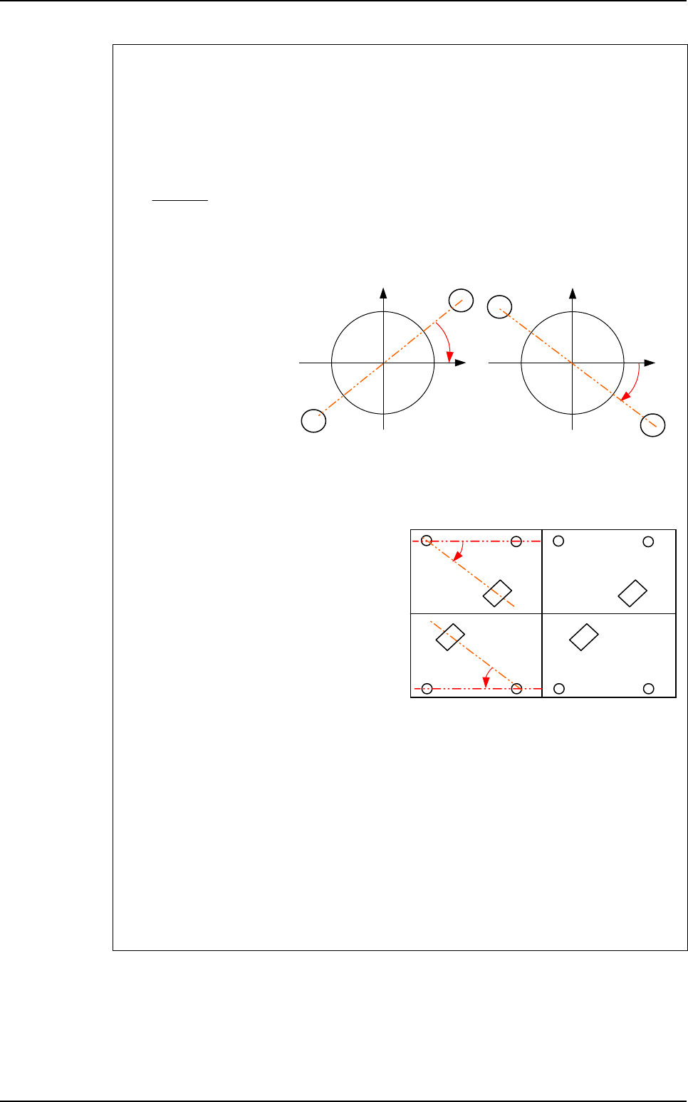
To know the expected value to enter in the .mod file
To calculate the expected angle between a component and a straight line, you need to
know the orientation of this line in the orthonormal referential (fiducials referencial).
The variable a is the slope of the straight line made by Topo1 and Topo2 in the
orthonormal referential because the line equation is:
Y = aX + b
a =
ρ
is the theoretical angle of the straight line in the .tst file.
ρ
= ARCTAN (a)
• If a > 0
⇒
θ
= T3 -
ρ
• If a < 0
⇒
θ
= T3 +
ρ
The expected angle is different for boards with different orientations in the .tst file.
In the .tst file:
• Board 1 & 3:
T3 = 315°
ρ
= 0°
⇒
θ
= 315°
• Board 2 & 4:
T3 = 135°
ρ
= 0°
⇒
θ
= 135°
In the .mod file:
• ANGLE_STRAIGHTLINE_TOPO1
• ORIENTATION-SENSORT1T2T33150.10.1
• ANGLE_STRAIGHTLINE_TOPO2
• ORIENTATION-SENSORT1T2T31350.10.1
• ANGLE_STRAIGHTLINE_TOPO3
• ORIENTATION-SENSORT1T2T33150.10.1
• ANGLE_STRAIGHTLINE_TOPO4
• ORIENTATION-SENSORT1T2T31350.10.1
Y2 - Y1
X2 - X1
Topo2
Topo1
a < 0
1
1
X
Y
Topo2
Y
Topo1
a > 0
1
1
X
Board 1
at 0°
Board 3
at 0°
Board 2
at 180°
Board 4
at 180°
Topo3
Topo3
Topo2Topo1 Topo2Topo1
Topo1Topo2 Topo1Topo2
θ
θ
Topo3
Topo3
Macros definition