VI User Manual.pdf - 第47页
Maintenance mode Vision 2007 4.10 User Manua l Rev 01 2 - 11 2.2.2 V ision tab The Pixel size ( A ) is directly obtained when the AOI sys tem is calibrated in the Test machine, Calibration menu . The Image features (Z on…
Maintenance mode
2 - 10 Vision 2007 4.10 User Manual Rev 01
2.2 Parameters
1. Click PARAMETERS button in the MODE MAINTENANCE menu to bring up the MACHINE PA-
RAMETERS window.
2. Click the tab to access the parameters that you want to view or modify.
3. Click OK button to confirm the values entered by default or the changes made and return to the
MODE MAINTENANCE menu.
4. Click Cancel button to leave the current procedure or return to the MODE MAINTENANCE menu.
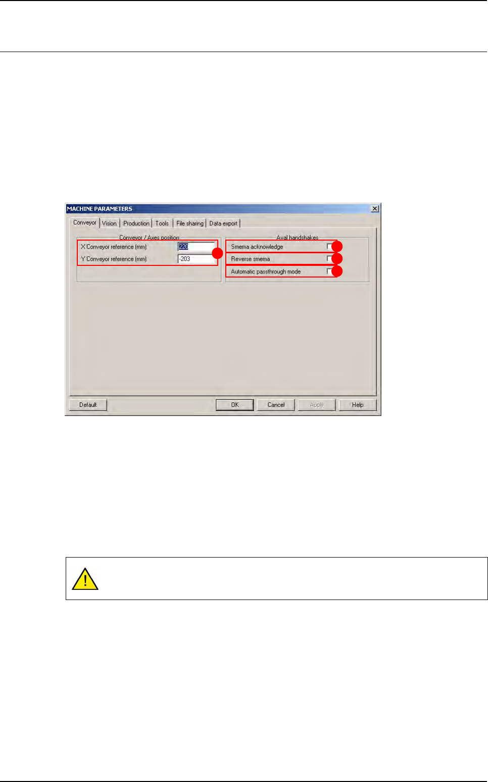
2.2.1 Conveyor tab
The XY conveyor references (A) are the distances between the axes 0 (position after initial-
ization) and the machine 0 (stop). If you change the position of the stop, these values must be
changed accordingly.
Tick Smema Acknowledge (B) to wait for acknowledgement of the downstream machine
(board received OK) in order to unload another board.
Tick Reverse Smema (C) to send the ready to send information to the downstream machine,
as soon as the output sensor is activated.
Tick Automatic passthrough mode (D) box to place the AOI system in the automatic
passthrough mode (by-pass).
If you have a fiducial or bar code error in production, the board will be sent to the down-
stream machine without any message.
A
B
C
D
Maintenance mode
Vision 2007 4.10 User Manual Rev 01 2 - 11
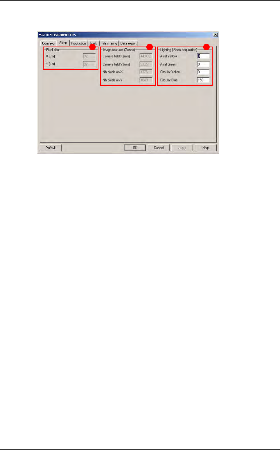
2.2.2 Vision tab
The Pixel size (A) is directly obtained when the AOI system is calibrated in the Test machine,
Calibration menu.
The
Image features (Zones)
(
B
) give the camera field of view. In the .tst files, the field of view
is called
Zone
.
Nb pixels …
gives the camera resolution (used to place the zones automatically).
Change the Lighting (Video acquisition) (C) parameters if you cannot see the image clearly
in the Cognex console when you move the camera with the AXIS mode in the MODE MAINTE-
NANCE.
B CA
Parameters
Maintenance mode
2 - 12 Vision 2007 4.10 User Manual Rev 01
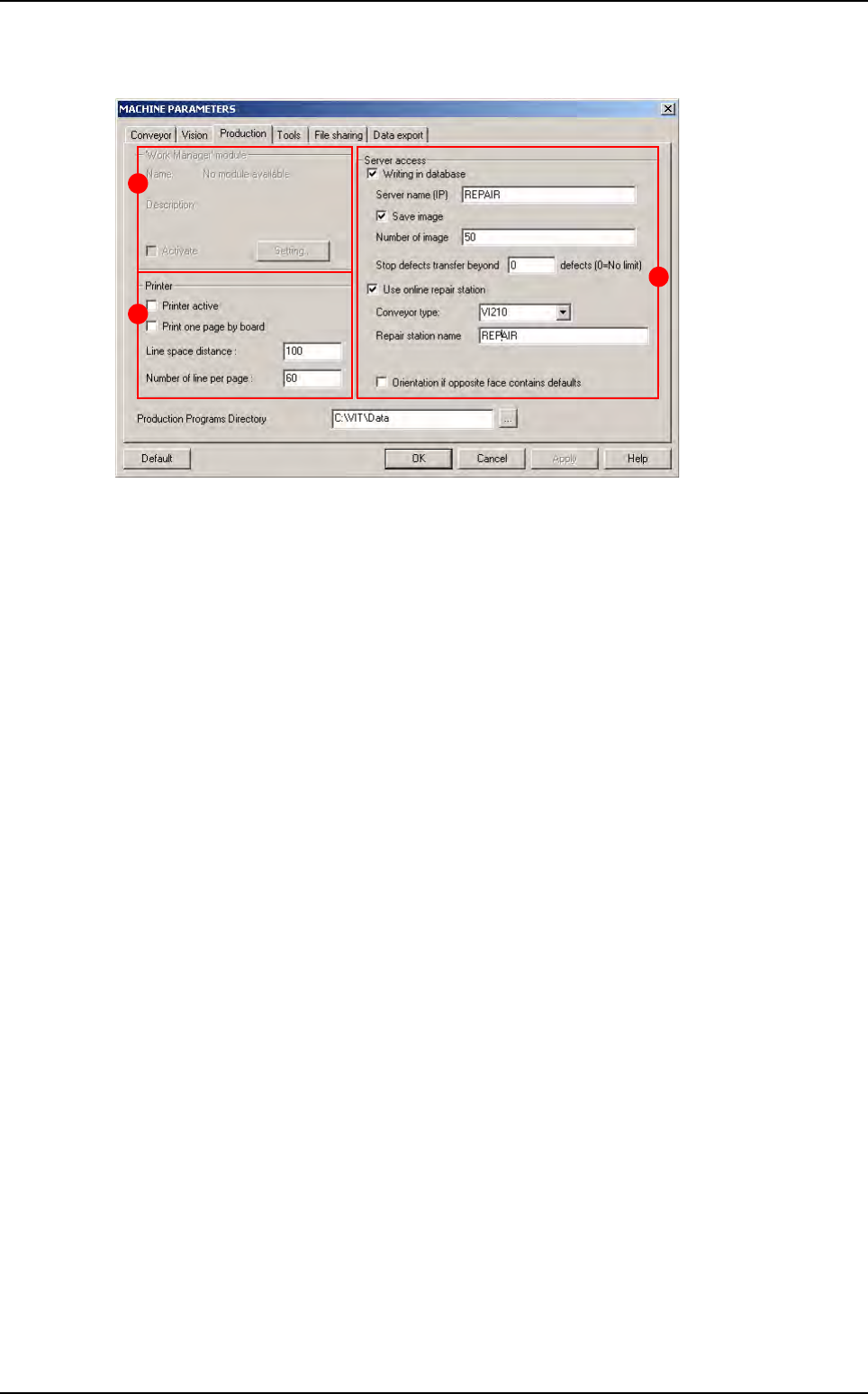
2.2.3 Production tab
In Work Manager module (A) (name by default when no module installed) section:
Tick Activate box to activate the customer extension module.
Click Setting... button to define the extension module.
In Printer (B) section:
Tick Printer active to connect the printer selected by default to the AOI system and thus
launch the printing of a list of faults detected by the machine during production.
Tick Print one page by board to obtain a paper print-out of each panel inspected during pro-
duction.
Line space distance: space between each line.
Number of line per page: number of line per page.
In Server access (C) section:
Tick Writing in database to save the inspection results in the supervision database:
• Server name (IP): name or IP address of the machine supervisor (use upper-case).
• Tick Save image to save images of the component defaults found in production, on the su-
pervisor computer.
• Number of image: number of images to transfer to repair station. It is also the number of
images for results table of the production screen (even if the number of images is less than
10 or if you do not active the Save image option, you will have 10 pictures in production).
• Stop defects transfer beyond ... defects: limit number of defects per panel to not transfer
the list of defects to the supervisor database.
Tick Use online repair station to repair the defaults online directly after inspection:
• Reparation name: name of the computer repair station (use upper-case).
• In Conveyor option:
- VI210: send good and bad boards on the same way.
- VI220 / VI210A: stop bad boards on the upper level waiting the operator reparation, while
good boards can carry on the production line.
- CO90B: direct bad boards on the repair station, while good boards can carry on the pro
duction line.
• Tick Orientation if opposite face contains faults to take into account the faults detected
by a previous AOI system when positioning the boards (in the case of a line with turning
over device for double-sided inspection).
A
B
C
Parameters