00198320-02_UM_ShuttleExtension-DE-EN-ZH.pdf - 第102页
Contents Assembly and User Manual Shuttle Extension Edition 11/2018 4 7.4.5 Step 5 . . . . . . . . . . . . . . . . . . . . . . . . . . . . . . . . . . . . . . . . . . . . . . . . . . . . . . . . . . . 83 7.4.6 Step 6 . .…
Assembly and User Manual SIPLACE TX Contents
Shuttle Extension Edition 11/2018
3
4.2 Assembly kit and mechanical connection . . . . . . . . . . . . . . . . . . . . . . . . . . . . . . . . . . . . . . . . . . . .53
4.2.1 General . . . . . . . . . . . . . . . . . . . . . . . . . . . . . . . . . . . . . . . . . . . . . . . . . . . . . . . . . 54
4.2.2 Adjustment . . . . . . . . . . . . . . . . . . . . . . . . . . . . . . . . . . . . . . . . . . . . . . . . . . . . . . . 55
4.2.3 Alignment and testing. . . . . . . . . . . . . . . . . . . . . . . . . . . . . . . . . . . . . . . . . . . . . . . 56
4.3 Electrical connections . . . . . . . . . . . . . . . . . . . . . . . . . . . . . . . . . . . . . . . . . . . . . . . . . . . . . . . . . . .57
4.3.1 Electrical connection on the shuttle extension . . . . . . . . . . . . . . . . . . . . . . . . . . . . 57
4.3.2 Electrical connection on the SIPLACE SX . . . . . . . . . . . . . . . . . . . . . . . . . . . . . . . 58
4.3.2.1 Mains interface connection. . . . . . . . . . . . . . . . . . . . . . . . . . . . . . . . . . . . . . . . . . . 58
4.3.2.2 SMEMA and CAN connections . . . . . . . . . . . . . . . . . . . . . . . . . . . . . . . . . . . . . . . 59
4.3.3 Circuit diagram . . . . . . . . . . . . . . . . . . . . . . . . . . . . . . . . . . . . . . . . . . . . . . . . . . . . 60
5 Calibration . . . . . . . . . . . . . . . . . . . . . . . . . . . . . . . . . . . . . . . . . . . . . . . . . . . . . . 61
5.1 Machine configuration . . . . . . . . . . . . . . . . . . . . . . . . . . . . . . . . . . . . . . . . . . . . . . . . . . . . . . . . . . .61
5.1.1 Update of embedded software . . . . . . . . . . . . . . . . . . . . . . . . . . . . . . . . . . . . . . . . 63
5.2 Perform Calibration . . . . . . . . . . . . . . . . . . . . . . . . . . . . . . . . . . . . . . . . . . . . . . . . . . . . . . . . . . . . .64
6 Operate the shuttle extension . . . . . . . . . . . . . . . . . . . . . . . . . . . . . . . . . . . . . . . 69
6.1 Shuttle extension on SIPLACE Pro . . . . . . . . . . . . . . . . . . . . . . . . . . . . . . . . . . . . . . . . . . . . . . . . .69
6.2 Shuttle extension on Station GUI. . . . . . . . . . . . . . . . . . . . . . . . . . . . . . . . . . . . . . . . . . . . . . . . . . .71
7 Barcode reader extension . . . . . . . . . . . . . . . . . . . . . . . . . . . . . . . . . . . . . . . . . . 75
7.1 Description and overview. . . . . . . . . . . . . . . . . . . . . . . . . . . . . . . . . . . . . . . . . . . . . . . . . . . . . . . . .75
7.1.1 Footprint . . . . . . . . . . . . . . . . . . . . . . . . . . . . . . . . . . . . . . . . . . . . . . . . . . . . . . . . . 76
7.2 Safety. . . . . . . . . . . . . . . . . . . . . . . . . . . . . . . . . . . . . . . . . . . . . . . . . . . . . . . . . . . . . . . . . . . . . . . .77
7.2.1 Warning labels . . . . . . . . . . . . . . . . . . . . . . . . . . . . . . . . . . . . . . . . . . . . . . . . . . . . 77
7.2.1.1 Warning label W 203 . . . . . . . . . . . . . . . . . . . . . . . . . . . . . . . . . . . . . . . . . . . . . . . 78
7.2.2 Classification of optical systems. . . . . . . . . . . . . . . . . . . . . . . . . . . . . . . . . . . . . . . 78
7.3 Scope of delivery . . . . . . . . . . . . . . . . . . . . . . . . . . . . . . . . . . . . . . . . . . . . . . . . . . . . . . . . . . . . . . .79
7.3.1 Overview - barcode reader extension kit assy. . . . . . . . . . . . . . . . . . . . . . . . . . . . 79
7.3.2 Shuttle extension loose parts . . . . . . . . . . . . . . . . . . . . . . . . . . . . . . . . . . . . . . . . . 80
7.4 Assembly Instruction . . . . . . . . . . . . . . . . . . . . . . . . . . . . . . . . . . . . . . . . . . . . . . . . . . . . . . . . . . . .81
7.4.1 Step 1. . . . . . . . . . . . . . . . . . . . . . . . . . . . . . . . . . . . . . . . . . . . . . . . . . . . . . . . . . . 81
7.4.2 Step 2. . . . . . . . . . . . . . . . . . . . . . . . . . . . . . . . . . . . . . . . . . . . . . . . . . . . . . . . . . . 81
7.4.3 Step 3. . . . . . . . . . . . . . . . . . . . . . . . . . . . . . . . . . . . . . . . . . . . . . . . . . . . . . . . . . . 82
7.4.4 Step 4. . . . . . . . . . . . . . . . . . . . . . . . . . . . . . . . . . . . . . . . . . . . . . . . . . . . . . . . . . . 82
Contents Assembly and User Manual
Shuttle Extension Edition 11/2018
4
7.4.5
Step 5 . . . . . . . . . . . . . . . . . . . . . . . . . . . . . . . . . . . . . . . . . . . . . . . . . . . . . . . . . . . 83
7.4.6 Step 6 . . . . . . . . . . . . . . . . . . . . . . . . . . . . . . . . . . . . . . . . . . . . . . . . . . . . . . . . . . . 83
7.4.7 Step 7 . . . . . . . . . . . . . . . . . . . . . . . . . . . . . . . . . . . . . . . . . . . . . . . . . . . . . . . . . . . 84
7.4.8 Step 8 . . . . . . . . . . . . . . . . . . . . . . . . . . . . . . . . . . . . . . . . . . . . . . . . . . . . . . . . . . . 84
7.4.9 Step 9 . . . . . . . . . . . . . . . . . . . . . . . . . . . . . . . . . . . . . . . . . . . . . . . . . . . . . . . . . . . 85
7.4.10 Step 10 . . . . . . . . . . . . . . . . . . . . . . . . . . . . . . . . . . . . . . . . . . . . . . . . . . . . . . . . . . 86
7.4.11 Step 11 . . . . . . . . . . . . . . . . . . . . . . . . . . . . . . . . . . . . . . . . . . . . . . . . . . . . . . . . . . 87
7.4.12 Step 12 . . . . . . . . . . . . . . . . . . . . . . . . . . . . . . . . . . . . . . . . . . . . . . . . . . . . . . . . . . 88
7.4.13 Step 13 . . . . . . . . . . . . . . . . . . . . . . . . . . . . . . . . . . . . . . . . . . . . . . . . . . . . . . . . . . 89
7.4.14 Barcode readers - overview . . . . . . . . . . . . . . . . . . . . . . . . . . . . . . . . . . . . . . . . . . 90
7.4.15 Barcode readers - wiring connection . . . . . . . . . . . . . . . . . . . . . . . . . . . . . . . . . . . 91
7.4.16 Barcode reader orientations and tilted angle . . . . . . . . . . . . . . . . . . . . . . . . . . . . . 92
7.5 Software installation and configuration . . . . . . . . . . . . . . . . . . . . . . . . . . . . . . . . . . . . . . . . . . . . . 92
7.6 Machine configuration . . . . . . . . . . . . . . . . . . . . . . . . . . . . . . . . . . . . . . . . . . . . . . . . . . . . . . . . . . 93
Assembly and Instruction Manual 1 Introduction
Shuttle Extension Edition 11/2018 1.1 Description
5
1 Introduction
This manual serves as an instruction guide or reference document for the assembly, operation
and configuration of the shuttle extension for SIPLACE TX and SIPLACE SX1/SX2 V2 machines.
1.1 Description
The shuttle extension enables a SIPLACE TX or SIPLACE SX1/SX2 V2 placement machine to be
connected to another machine with a different conveyor mode. The shuttle extension balances the
positions of the fixed rail in the various conveyor modes (I-Placement to alternating) and regulates
the lane accuracy during transportation of the boards. It is also possible to connect a dual con
-
veyor to a single conveyor and vice versa. In addition, you can also connect a supplementary pro
-
duction device (such as a printer or furnace), which has a different conveyor mode to the SIPLACE
TX / SIPLACE SX1/SX2 V2.
1
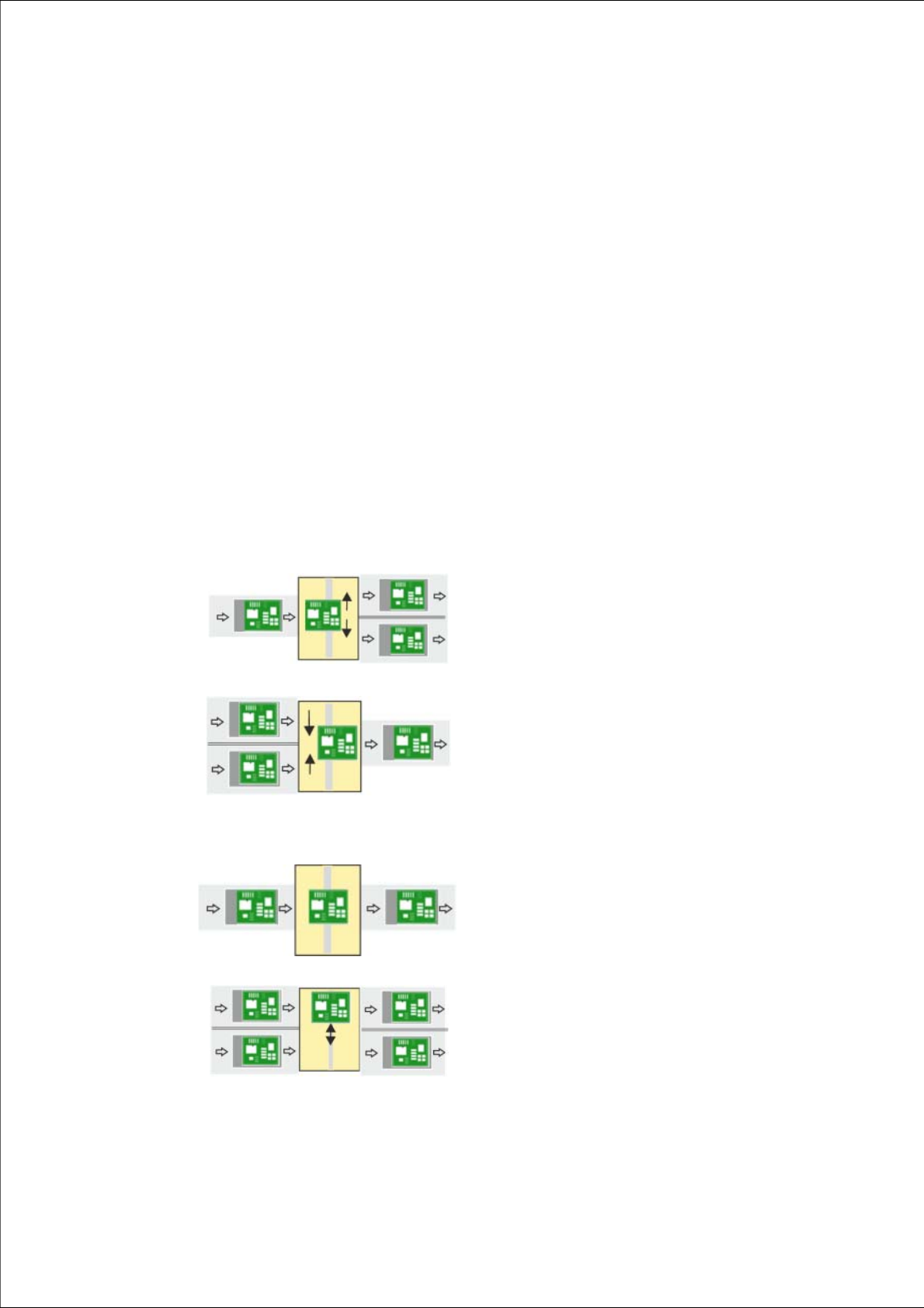
Single conveyor => dual conveyor
Usually, the following right and then left conveyor lane are
used in alternation. However, if a conveyor lane is
blocked, the other lane can also be used several times in
succession.
1
Dual conveyor => single conveyor
Usually, pickup is from the right and then the left conveyor
lane of the previous machine, in alternation. However, if
there is a problem at one lane or if there is no board
available, pickup can also be from the other lane several
times in succession. Precondition: the same product must
be produced on both lanes
1
Single conveyor => single conveyor
The boards are transported through.
A displacement of the two machines can, for example, be
compensated for in this case.
1
Dual conveyor => dual conveyor
Transfer of board with lane accuracy: The boards from
conveyor lane 1 are also transported in conveyor lane 1
of the next machine. Usually, the conveyor lanes are used
in alternation.