00198320-02_UM_ShuttleExtension-DE-EN-ZH.pdf - 第187页
Assembly and Instruction Manual 7 Barcode reader extension Shuttle Extension Edition 11/2018 7.4 Assembly Instruction 89 7.4.15 Barcode r eaders - wiring connection 7 Fig. 7.4 - 15 Barcode readers - wiring connection

7 Barcode reader extension Assembly and Instruction Manual
7.4 Assembly Instruction Shuttle Extension Edition 11/2018
88
7.4.14 Barcode readers - overview
The standard scan distance for the barcode reader is 80 mm from the PCB surface. Nonetheless,
both top and bottom barcode reader assembly can be adjusted to 60mm to allow reading smaller
code cells.
7
Fig. 7.4 - 14 Barcode readers - overview
Assembly kit PCB barcode
top
Assembly kit PCB bar
-
code bottom
PCB
Rail extension + belt+ pulleys
Assembly and Instruction Manual 7 Barcode reader extension
Shuttle Extension Edition 11/2018 7.4 Assembly Instruction
89
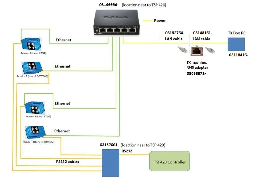
7.4.15 Barcode readers - wiring connection
7
Fig. 7.4 - 15 Barcode readers - wiring connection
7 Barcode reader extension Assembly and Instruction Manual
7.5 Software installation and configuration Shuttle Extension Edition 11/2018
90
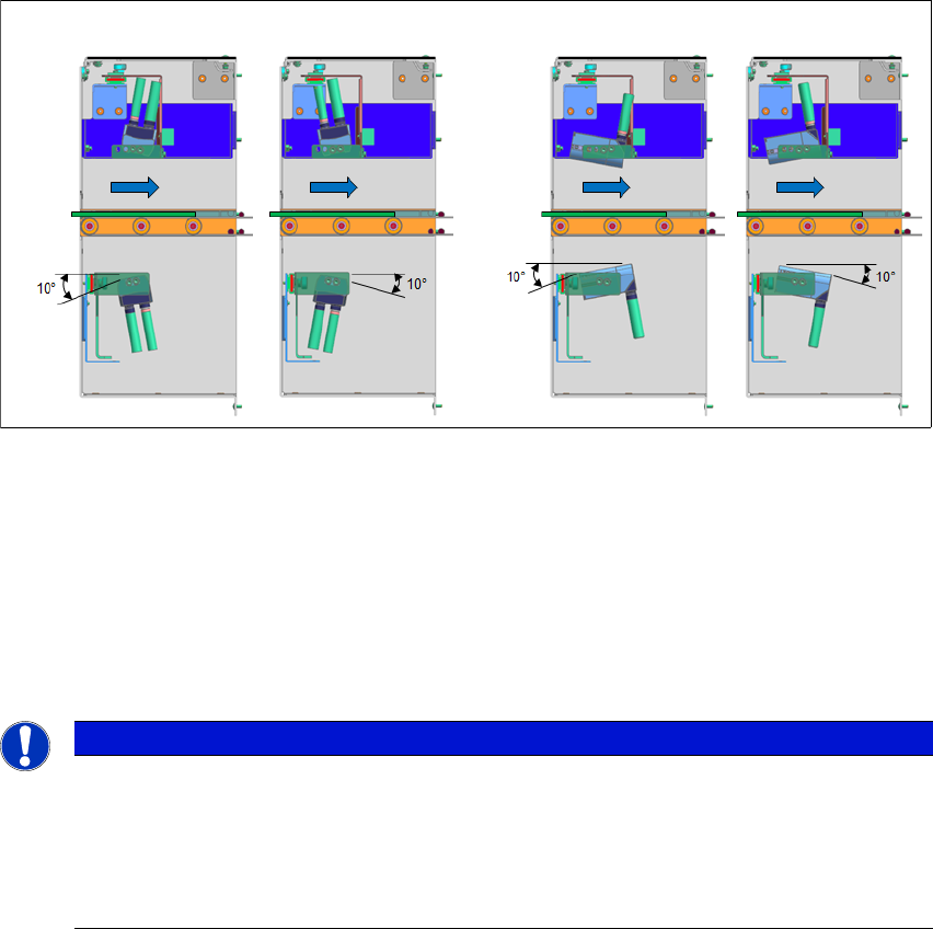
7.4.16 Barcode reader orientations and tilted angle
The barcode readers can be mounted in two orientations and be tilted ±10° all round.
7
Fig. 7.4 - 16 Barcode reader orientations and tilted angle
7.5 Software installation and configuration
To install the SICK software "SOPAS" and to configure the 2D LECTOR 620 PCB barcode scan
-
ner, see the "Installation and Configuration Barcode Scanner SICK" manual [DE: 00198202 xx]
[EN: 00198203 xx].
7
Vertical mount
Horizontal mount
PCB
Direction
PCB
Direction
PLEASE NOTE
Further information
For more information, please contact the SIPLACE service with reference to the following
numbers:.
– TI2016-05V03 / TI2016-05C03
– TI2015-12V06 / TI2015-12C06