00198320-02_UM_ShuttleExtension-DE-EN-ZH.pdf - 第132页
2 Operational safety Assembly and Instruction Manual 2.4 Transporting the shuttle ext ension Shuttle Extension Edition 11/2018 34 2.4 Transporting the shuttle extension Fig. 2.4 - 1 Transporting the shuttle extension T…

Assembly and Instruction Manual 2 Operational safety
Shuttle Extension Edition 11/2018 2.3 Safety
33
2.3.2.3 Description of functions
Stop button, black (item 1 in fig.
2.3 - 2, page 31 2
These button is used to stop the shuttle extension. The electromagnetic lock is released and the
top cover can be opened.
Start button, green (item 2 in fig. 2.3 - 2, page 31 2
Press the Start button for at least 200 ms, up to a maximum of 1500 ms, and then let go. The
shuttle extension is switched on and the top cover is locked when you let go of the button.
EMERGENCY STOP button with forced locking (item 3 in fig. 2.3 - 2, page 31 2
The EMERGENCY STOP button is red and latches in the ON position when pressed. When you
press the EMERGENCY STOP button, the switching contact of the EMERGENCY STOP circuit
of the shuttle extension opens and the shuttle extension stops. The signaling contact for the
EMERGENCY STOP button will open and a message will be shown in the station software for the
SIPLACE machine.
Top cover protective switch (item 2 in fig. 2.3 - 3, page 32) 2
This switch check whether the top cover is closed. If it is closed, the EMERGENCY STOP button
and the signaling contact will be closed. If the top cover is opened, the EMERGENCY STOP con
-
tact and the signaling contact will open.
Electromagnetic lock (item 1 in fig. 2.3 - 3, page 32) 2
The electromagnetic lock check whether the top cover is closed. If it is closed, the EMERGENCY
STOP button and the signaling contact will be closed.
Pulling the top cover downwards, the electromagnetic lock prevent operator to opening it. The
electromagnetic lock can be deactivated by pressing the stop button of the shuttle extension, or
breaking the safety loop by opening the safety switch or pressing the EMERGENCY STOP button.
2 Operational safety Assembly and Instruction Manual
2.4 Transporting the shuttle extension Shuttle Extension Edition 11/2018
34
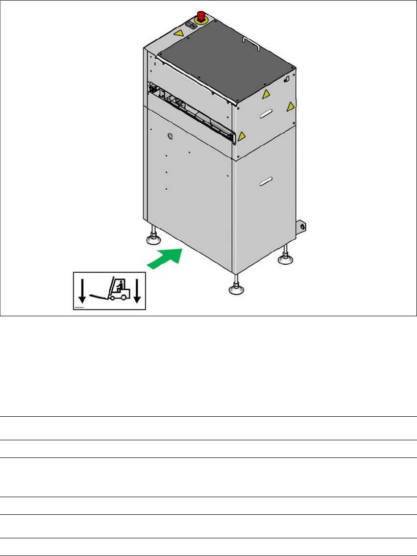
2.4 Transporting the shuttle extension
Fig. 2.4 - 1 Transporting the shuttle extension
The shuttle extension may ONLY be lifted with a pallet jack on the side (A).
2.4.1 Shipping packaging and transportation equipment
2
(A)
Shipping packaging dimensions (L x W x H)
Pallet 1105 mm x 905 mm x 1535 mm
Weight of the shuttle extension when ready for dispatch
With two shuttle extensions
170 kg
Transportation equipment
Pallet jack with fork length 700 mm

Assembly and Instruction Manual 2 Operational safety
Shuttle Extension Edition 11/2018 2.5 ESD guidelines
35
2.5 ESD guidelines
2.5.1 What does ESD mean?
Almost all of the modules in use today are equipped with highly integrated MOS blocks and com
-
ponents. The manufacturing techniques used mean that these electronic components are ex
-
tremely sensitive to overvoltage and thus to electrostatic discharge.
The abbreviation for such modules is 'ESD' (Electrostatic Sensitive Device). ’ESD’ is used inter
-
nationally. The following symbol on cabinet typeplates, racks or packaging indicates that compo
-
nents which are sensitive to electrostatic discharge have been used and that the modules
concerned are also touch-sensitive.
ESDs can be destroyed by voltages and power levels that are far below the level
that can be perceived by humans. Such voltages occur if a person touches a com
-
ponent or module without earthing themselves. Components that are exposed to
such overvoltages do not generally appear to be defective immediately - incorrect
behavior starts after the component or module has been in operation for some time.
2.5.2 Important measures to protect against static charging
Most plastics can easily become charged and must therefore be kept away from at-risk com
-
ponents.
Always ensure that people, the workplace and packaging are safely earthed when handling
electrostatic sensitive components.