00198320-02_UM_ShuttleExtension-DE-EN-ZH.pdf - 第146页
3 Assembly on the SIPLACE TX Assembly and Instruction Manual 3.4 Electrical connections Shuttle Extension Edition 11/2018 48 3.4.2 Electrical connec tion on the SIPLACE TX 3.4.2.1 Overview Fig. 3.4 - 2 SIPLACE TX connect…
Assembly and Instruction Manual 3 Assembly on the SIPLACE TX
Shuttle Extension Edition 11/2018 3.4 Electrical connections
47
3.4 Electrical connections
3
3.4.1 Electrical connection on the shuttle extension
Connect the following cables to the shuttle extension connection.
– 4 x SMEMA cable [Item. No.: 03152800-xx]
– 1 x CAN bus cable [Item. No.: 03133551-xx]
– 1 x Power interface cable to SIPLACE TX [Item. No. 03133550-xx]
Fig. 3.4 - 1 Electrical connection on the shuttle extension
(1) SMEMA connection XL1 UPSTREAM - lane 1 to machine before
(2) SMEMA connection XL2 UPSTREAM - lane 2 to machine before
(3) CAN-BUS connection
(4) SMEMA connection XL2 DOWNSTREAM - lane 2 to next machine
(5) SMEMA connection XL1 DOWNSTREAM - lane 1 to next machine
(6) POWER interface X50 to SIPLACE TX
PLEASE NOTE
Use of the circuit diagrams of the shuttle extension
For detail information, please refer to the circuit diagrams of the shuttle extension.
(6)
(1)
(2)
(3)
(4)
(5)
3 Assembly on the SIPLACE TX Assembly and Instruction Manual
3.4 Electrical connections Shuttle Extension Edition 11/2018
48
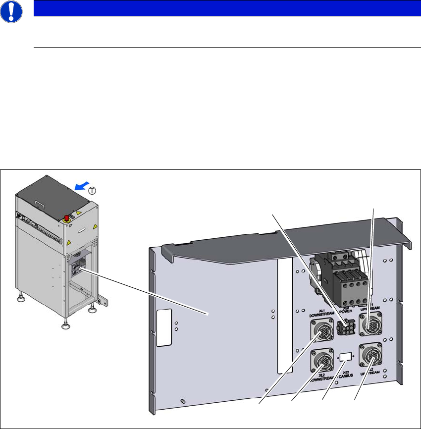
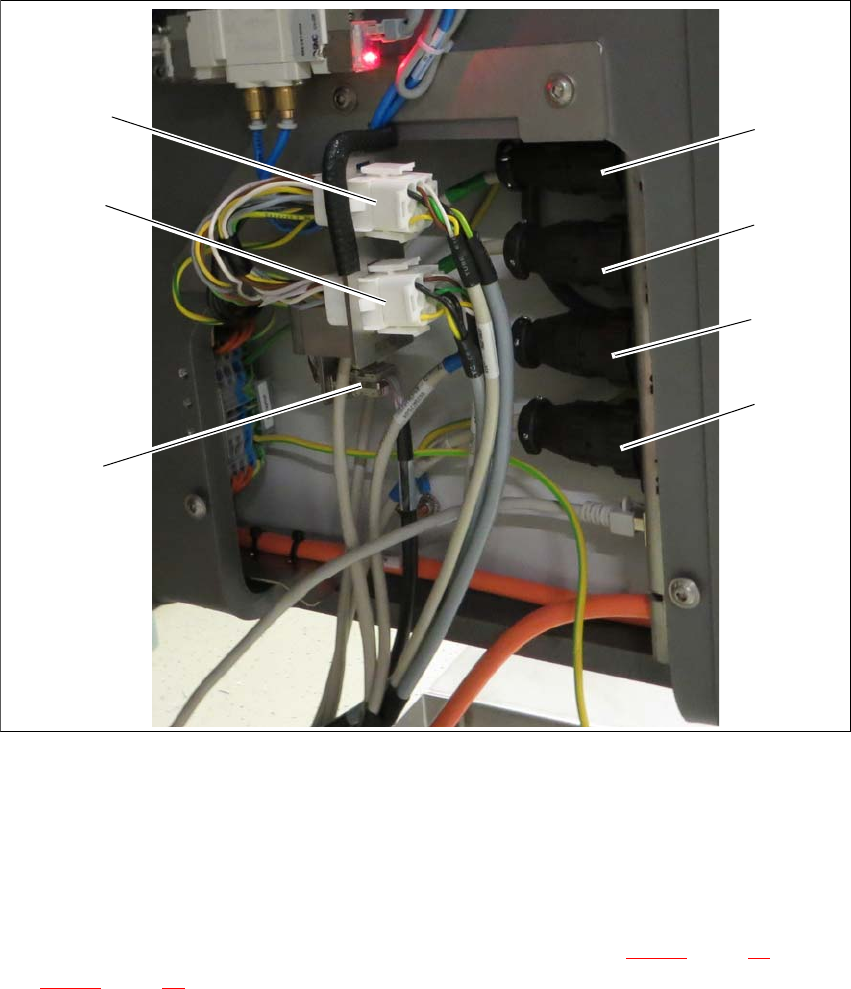
3.4.2 Electrical connection on the SIPLACE TX
3.4.2.1 Overview
Fig. 3.4 - 2 SIPLACE TX connection
(1) SMEMA connection T1 UPSTREAM
(2) SMEMA connection T1 DOWNSTREAM
(3) SMEMA connection T2 UPSTREAM
(4) SMEMA connection T2 DOWNSTREAM
(5) CAN-BUS connection (for termination and connection see section 3.4.2.2
, page 49 and
3.4.2.3
, page 50)
(6) Power interface to the output shuttle extension
(7) Power interface to the input shuttle extension
(7)
(6)
(5)
(1)
(2)
(3)
(4)

Assembly and Instruction Manual 3 Assembly on the SIPLACE TX
Shuttle Extension Edition 11/2018 3.4 Electrical connections
49
3.4.2.2 Connections
The shuttle extension supports two configurations: upstream and downstream, the wiring and
jumper settings are specified as follows:
3
For special configurations where two shuttle extensions are link to a single SIPLACE TX machine,
the CAN cable and TSP 420 jumper setting will be configure as per below.
3
Upstream configurations Downstream configurations
Power connection to TX -X15.S1 -X15.S2
CAN Bus connection to TX CAN3.EXT CAN3.EXT
Power connection to TX X50 X50
CAN bus connection to shuttle X52 X52
SMEMA connection to TX -XL1 and XL2 upstream -XL1 and XL2 upstream
SMEMA connection to shuttle -XL1-DS and XL2-DS (down
-
stream)
-XL1-US and XL2-US
(Upstream)
TSP 420 jumper setting JP1 pin 2 and 3 is shorted
JP2 pin 1 and 2 is shorted
JP1 pin 2 and 3 is shorted
JP2 pin 1 and 2 is shorted
CAN termination connector re
-
moved from CAN3.EXT
Plugged into -X1* (CAN ca
-
ble: upstream)
Plugged into -X1* (CAN ca
-
ble: downstream)
CAN cable IDC connector Upstream configurations Downstream
configurations
-X1 -X1*(cable: downstream) CAN3.EXT (TX)
-X1* CAN termination connector
removed from CAN3.EXT
-X1 (cable: upstream)
-X52 -X52 (shuttle upstream) -X52 (shuttle upstream)
TSP 420 jumper setting
JP1 pin 2 and 3 is shorted
JP2 pin 1 and 2 is shorted
JP1 pin 2 and 3 is shorted
JP2 pin 1 and 2 is shorted