00198320-02_UM_ShuttleExtension-DE-EN-ZH.pdf - 第179页
Assembly and Instruction Manual 7 Barcode reader extension Shuttle Extension Edition 11/2018 7.4 Assembly Instruction 81 7.4.5 Step 5 Mount 0 3149525- synchronous belt 2.5x2.2 AT3/1341 onto the le ft rail and tension i…
7 Barcode reader extension Assembly and Instruction Manual
7.4 Assembly Instruction Shuttle Extension Edition 11/2018
80
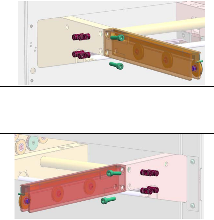
7.4.3 Step 3
Mount the pre-assembled extension rail_left onto the shuttle conveyor via 2x 03116105-Bolt
4 M-C, 2x 03116106-Bolt 5 M-C and 2x 03042563-ISO4762 M5x20.
Fig. 7.4 - 3 Step 3
7.4.4 Step 4
Mount the pre-assembled extension rail_right onto the shuttle conveyor via 2x 03116105-Bolt
4 M-C, 2x 03116106-Bolt 5 M-C and 2x 03042563-ISO4762 M5x20.
Fig. 7.4 - 4 Step 4
Assembly and Instruction Manual 7 Barcode reader extension
Shuttle Extension Edition 11/2018 7.4 Assembly Instruction
81
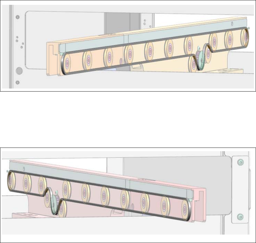
7.4.5 Step 5
Mount 03149525- synchronous belt 2.5x2.2 AT3/1341 onto the left rail and tension it accord
-
ingly.
Fig. 7.4 - 5 Step 5
7.4.6 Step 6
Mount 03149525- synchronous belt 2.5x2.2 AT3/1341 onto the right rail and tension it accord
-
ingly.
Fig. 7.4 - 6 Step 6
7 Barcode reader extension Assembly and Instruction Manual
7.4 Assembly Instruction Shuttle Extension Edition 11/2018
82
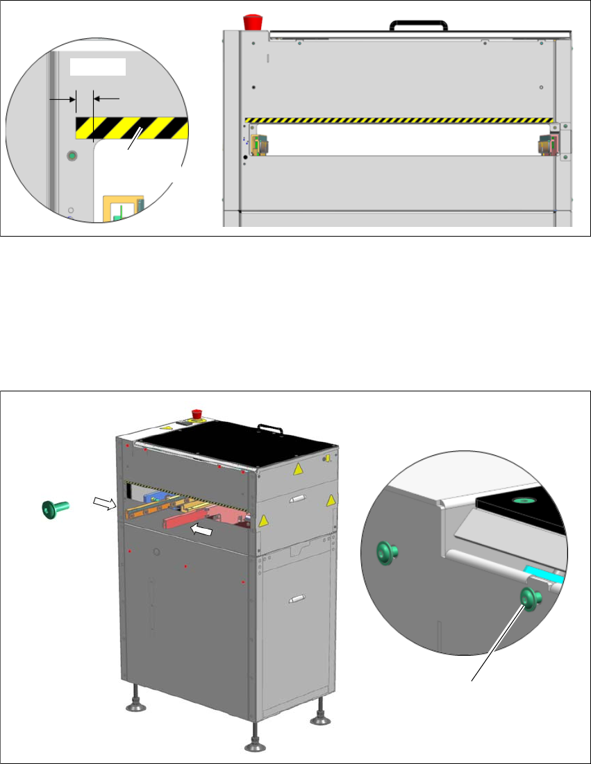
7.4.7 Step 7
Place 03153427- safety mark 9x600mm onto the shuttle machine frame on the input side
only.
Fig. 7.4 - 7 Step 7
7.4.8 Step 8
Mount 7x button head screws 03099579- ISO7380-2 M4x10-A2-70 onto the machine frame
and fasten them loosely so that barcode reader cover can slide through the key holes.
Move the conveyor rails towards the center of the shuttle extension for easier cover insertion.
Fig. 7.4 - 8 Step 8
Aligned flush
7.5 mm
Fasten screws loosley to allow
cover insertion
7x 03099579
ISO7380-2 M4x10