00198320-02_UM_ShuttleExtension-DE-EN-ZH.pdf - 第145页
Assembly and Instruction Manual 3 Assembly on the SIPLACE TX Shuttle Extension Edition 11/2018 3.4 Electrical connections 47 3.4 Electrical connections 3 3.4.1 Electrical connection on the shuttle extension Connect the…

3 Assembly on the SIPLACE TX Assembly and Instruction Manual
3.3 Assembly kit and mechanical connection Shuttle Extension Edition 11/2018
46
Finalize 3
Leave a gap of 2 mm to 8 mm between the frame of the SIPLACE TX and the frame of the
shuttle extension. See fig. 3.2 - 1
, page 38.
Check the transition between the shuttle extension and the SIPLACE TX again.
If necessary, correct the height at the feet or the fixture of the interface brackets.
Once the shuttle extension has been correctly aligned, tighten the top nuts (item 1 in fig. 3.3
- 4, page 41) to clamp all shuttle extension feet.
Assembly and Instruction Manual 3 Assembly on the SIPLACE TX
Shuttle Extension Edition 11/2018 3.4 Electrical connections
47
3.4 Electrical connections
3
3.4.1 Electrical connection on the shuttle extension
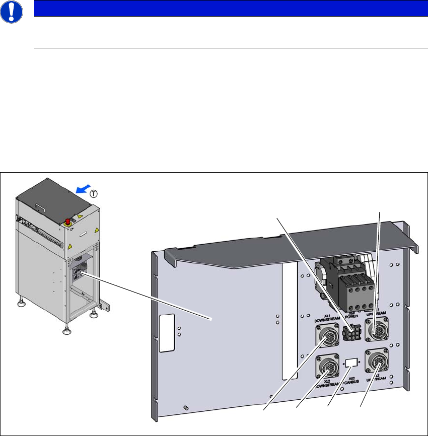
Connect the following cables to the shuttle extension connection.
– 4 x SMEMA cable [Item. No.: 03152800-xx]
– 1 x CAN bus cable [Item. No.: 03133551-xx]
– 1 x Power interface cable to SIPLACE TX [Item. No. 03133550-xx]
Fig. 3.4 - 1 Electrical connection on the shuttle extension
(1) SMEMA connection XL1 UPSTREAM - lane 1 to machine before
(2) SMEMA connection XL2 UPSTREAM - lane 2 to machine before
(3) CAN-BUS connection
(4) SMEMA connection XL2 DOWNSTREAM - lane 2 to next machine
(5) SMEMA connection XL1 DOWNSTREAM - lane 1 to next machine
(6) POWER interface X50 to SIPLACE TX
PLEASE NOTE
Use of the circuit diagrams of the shuttle extension
For detail information, please refer to the circuit diagrams of the shuttle extension.
(6)
(1)
(2)
(3)
(4)
(5)
3 Assembly on the SIPLACE TX Assembly and Instruction Manual
3.4 Electrical connections Shuttle Extension Edition 11/2018
48
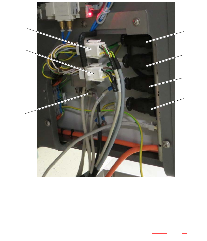
3.4.2 Electrical connection on the SIPLACE TX
3.4.2.1 Overview
Fig. 3.4 - 2 SIPLACE TX connection
(1) SMEMA connection T1 UPSTREAM
(2) SMEMA connection T1 DOWNSTREAM
(3) SMEMA connection T2 UPSTREAM
(4) SMEMA connection T2 DOWNSTREAM
(5) CAN-BUS connection (for termination and connection see section 3.4.2.2
, page 49 and
3.4.2.3
, page 50)
(6) Power interface to the output shuttle extension
(7) Power interface to the input shuttle extension
(7)
(6)
(5)
(1)
(2)
(3)
(4)