00198320-02_UM_ShuttleExtension-DE-EN-ZH.pdf - 第143页
Assembly and Instruction Manual 3 Assembly on the SIPLACE TX Shuttle Extension Edition 11/2018 3. 3 Assembly kit and mechanical connection 45 Interface brackets on output shuttle extension side 3 Fig. 3.3 - 10 Interface …
3 Assembly on the SIPLACE TX Assembly and Instruction Manual
3.3 Assembly kit and mechanical connection Shuttle Extension Edition 11/2018
44
It must be possible to push the board through easily and with no resistance.
Screw the shuttle extension onto TX machine via interface brackets to secure in place.
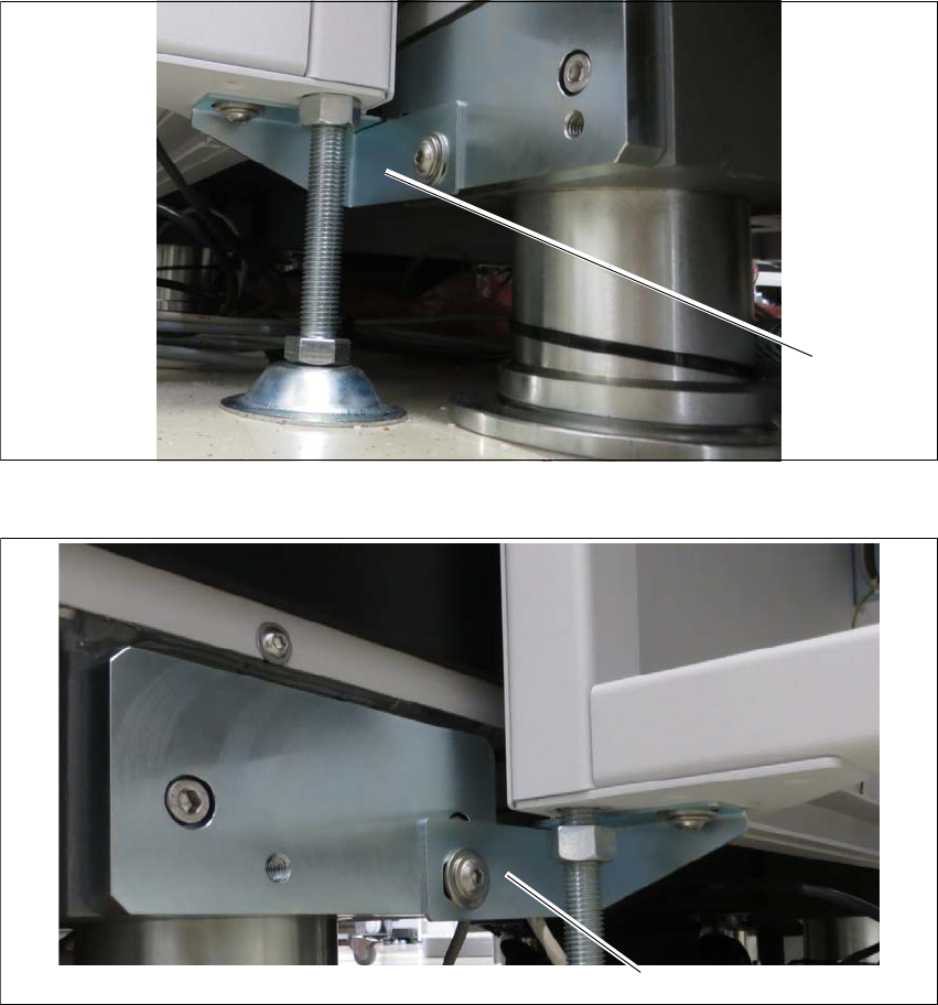
Interface brackets on input shuttle extension side 3
Fig. 3.3 - 8 Interface bracket on input conveyor - right side
Fig. 3.3 - 9 Interface bracket on input conveyor - left side
(1) Interface bracket input conveyor - right side
(2) Interface bracket input conveyor - left side
(1)
(2)
Assembly and Instruction Manual 3 Assembly on the SIPLACE TX
Shuttle Extension Edition 11/2018 3.3 Assembly kit and mechanical connection
45
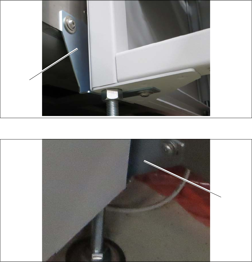
Interface brackets on output shuttle extension side 3
Fig. 3.3 - 10 Interface brackets on output conveyor - left side
Fig. 3.3 - 11 Interface brackets on output conveyor - right side
(1) Interface bracket output conveyor - left side
(2) Interface bracket output conveyor - right side
(1)
(2)

3 Assembly on the SIPLACE TX Assembly and Instruction Manual
3.3 Assembly kit and mechanical connection Shuttle Extension Edition 11/2018
46
Finalize 3
Leave a gap of 2 mm to 8 mm between the frame of the SIPLACE TX and the frame of the
shuttle extension. See fig. 3.2 - 1
, page 38.
Check the transition between the shuttle extension and the SIPLACE TX again.
If necessary, correct the height at the feet or the fixture of the interface brackets.
Once the shuttle extension has been correctly aligned, tighten the top nuts (item 1 in fig. 3.3
- 4, page 41) to clamp all shuttle extension feet.