00198320-02_UM_ShuttleExtension-DE-EN-ZH.pdf - 第152页
4 Assembly on the SIPLACE SX V2 Assembly and Instruction Manual 4.2 Assembly kit and mechanical connection Shuttle Extension Edit ion 11/2018 54 4.2.3 Alignment and testing Align one of the shuttle conveyor sides (eith…
Assembly and Instruction Manual 4 Assembly on the SIPLACE SX V2
Shuttle Extension Edition 11/2018 4.2 Assembly kit and mechanical connection
53
4.2.2 Adjustment
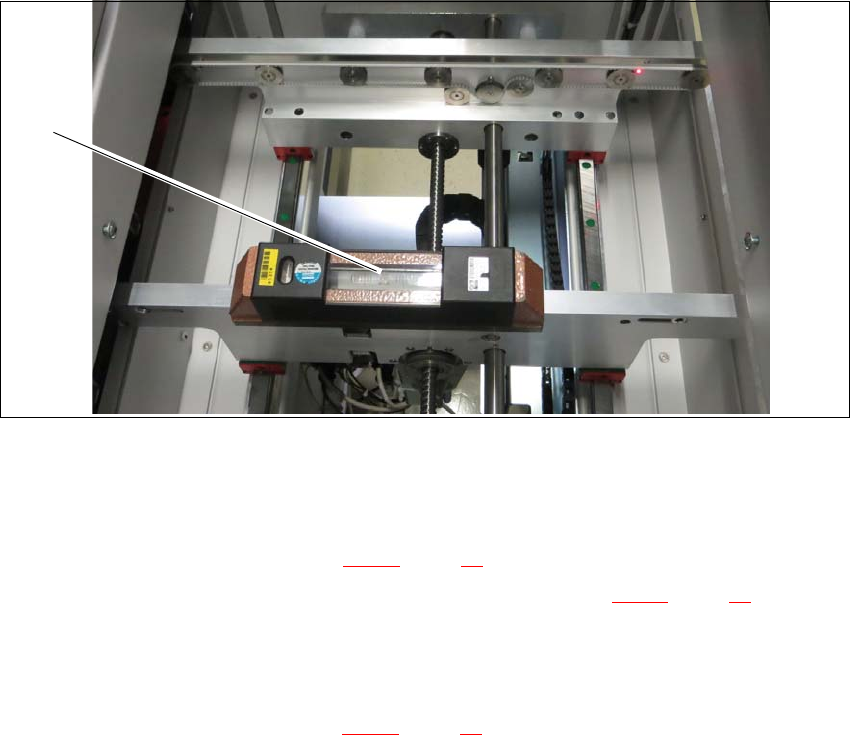
Place a machine spirit level (measuring accuracy of 0.02 mm) against the edge of the shuttle
extension PCB conveyor.
Fig. 4.2 - 2 Machine spirit level measuring accuracy of 0.02 mm) on conveyor rail
Use the machine spirit level (1) to align the shuttle extension in the X and Y direction, at the
four machine feet.
Unscrew the top nut (item 1 in fig. 4.2 - 1, page 52) with the help of a s open-ended wrench.
Use the open-ended wrench to set the bottom nuts (item 2 in fig. 4.2 - 1, page 52) of all four
shuttle extension feet, so that the fluid in the machine spirit level does not deviate from its
zero point at the required conveyor height.
Check the required board conveyor height.
Tighten the top nuts (item 1 in fig. 4.2 - 1, page 52) to clamp all shuttle extension feet.
(1)
4 Assembly on the SIPLACE SX V2 Assembly and Instruction Manual
4.2 Assembly kit and mechanical connection Shuttle Extension Edition 11/2018
54
4.2.3 Alignment and testing
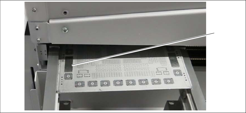
Align one of the shuttle conveyor sides (either left or right) to the SX conveyor side.
Fig. 4.2 - 3 Check PCB
Check rail position with the calibrated PCB.
Push a board through the PCB conveyor and check the transition point between the shuttle
extension and the SIPLACE SX.
It must be possible to push the board through easily and with no resistance.
(1)
Assembly and Instruction Manual 4 Assembly on the SIPLACE SX V2
Shuttle Extension Edition 11/2018 4.3 Electrical connections
55
4.3 Electrical connections
4
4.3.1 Electrical connection on the shuttle extension
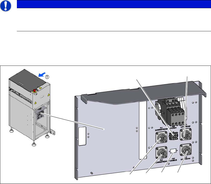
Connect the following cables to the shuttle extension connection.
Fig. 4.3 - 1 Electrical connection on the shuttle extension
(1) SMEMA connection XL1 UPSTREAM - lane 1 to predecessor machine
(2) SMEMA connection XL2 UPSTREAM - lane 2 to predecessor machine
(3) CAN-BUS connection
(4) SMEMA connection XL2 DOWNSTREAM - lane 2 to next machine
(5) SMEMA connection XL1 DOWNSTREAM - lane 1 to next machine
(6) MAINS interface X50 for SIPLACE SX
PLEASE NOTE
Use of the circuit diagrams of the shuttle extension
For detailed information please consult the circuit diagram for the shuttle extension
and the wiring diagram provided in Section 4.3.3 on page 58.
(6)
(1)
(2)
(3)
(4)
(5)