00198320-02_UM_ShuttleExtension-DE-EN-ZH.pdf - 第149页
Assembly and Instruction Manual 4 Assembly on the SIPLACE SX V2 Shuttle Extension Edition 11/2018 4.1 Scope of delivery 51 4 Assembly on the SIPLACE SX V2 4.1 Scope of delivery – Extension kit shuttle on SX2: Item no.:03…
3 Assembly on the SIPLACE TX Assembly and Instruction Manual
3.4 Electrical connections Shuttle Extension Edition 11/2018
50
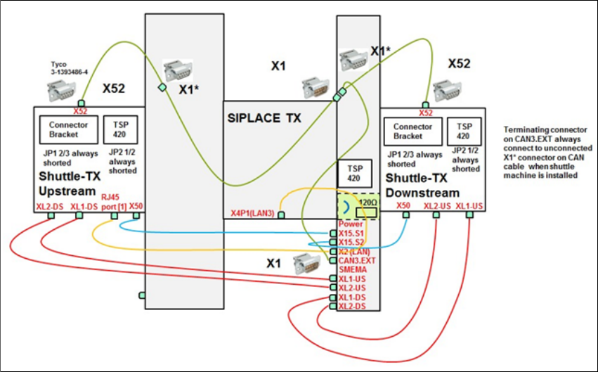
3.4.2.3 CAN cable connections for special configuration
Fig. 3.4 - 3 CAN cable connections for special configuration

Assembly and Instruction Manual 4 Assembly on the SIPLACE SX V2
Shuttle Extension Edition 11/2018 4.1 Scope of delivery
51
4 Assembly on the SIPLACE SX V2
4.1 Scope of delivery
– Extension kit shuttle on SX2: Item no.:03167757-xx
– Power cable to shuttle extension: Item no.:03133550-01-xx
– CAN cable to shuttle extension: Item no.:03133551-xx
– Connection cable to SX2 shuttle opt: Item no.:03170059-xx
4.2 Assembly kit and mechanical connection
There are currently no plans for a mechanical connection between the SIPLACE SX and the shut
-
tle extension. The shuttle extension is positioned at the SIPLACE so that the board can be trans
-
ported through the PCB conveyor.
Push a board through the PCB conveyor and check the transition point between the shuttle
extension and the SIPLACE SX.
It must be possible to push the board through easily and with no resistance.
4 Assembly on the SIPLACE SX V2 Assembly and Instruction Manual
4.2 Assembly kit and mechanical connection Shuttle Extension Edition 11/2018
52
4.2.1 General
Remove the four side covers from the shuttle extension. This gives you access to the fixtures
for the interface brackets and the electrical connection.
Move the shuttle extension to the SIPLACE SX.
Set the height of the shuttle extension, so that the PCB conveyor for the shuttle extension is
the same height as the PCB conveyor for the SIPLACE SX.
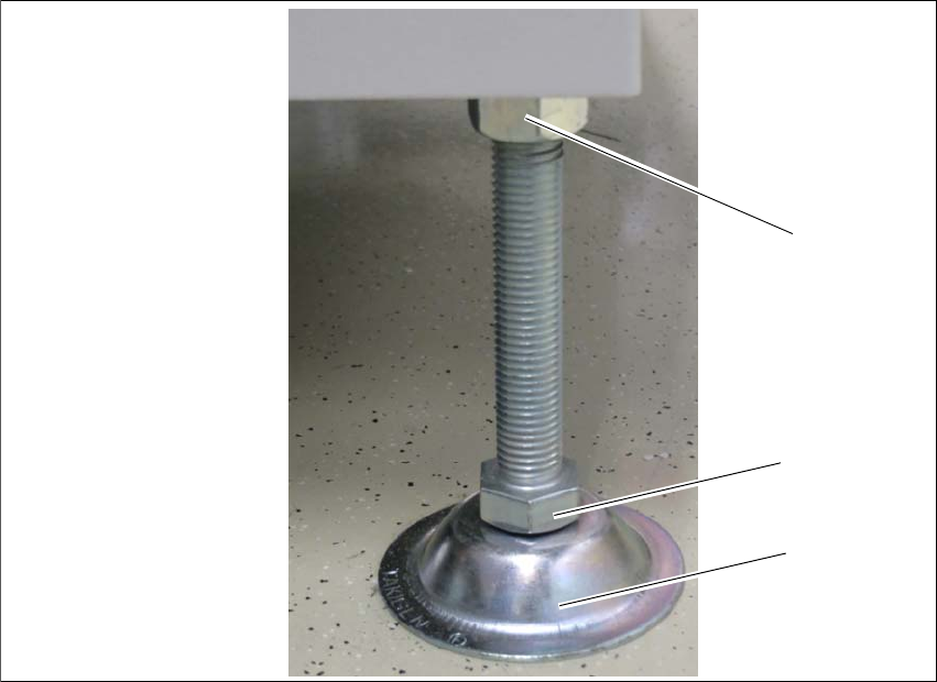
The shuttle extension stands on 4 feet.
Fig. 4.2 - 1 Presetting the height of the machine feet
(1) Top screw nut
(2) Bottom screw nut
(3) Shuttle extension feet
Turn the shuttle extension feet (3) with the bottom screw nut (2) so that the shuttle extension
has the same height as the PCB conveyor height of the SIPLACE SX.
Tighten the top screw nut (1), so that the machine feet are fixed into place.
Check the height of the shuttle extension and correct the height, if necessary.
(1)
(2)
(3)