00198320-02_UM_ShuttleExtension-DE-EN-ZH.pdf - 第167页
Assembly and Instruction Manual 6 Operate the shuttle extension Shuttle Extension Edition 11/2018 6.2 Shuttle extension on Statio n GUI 69 6.2 Shuttle extension on Station GUI Each shuttle extension is cont ro lled via t…
6 Operate the shuttle extension Assembly and Instruction Manual
6.1 Shuttle extension on SIPLACE Pro Shuttle Extension Edition 11/2018
68
Edit field: Input conveyor 6
– Shuttle
– The station has a SIPLACE TX conveyor shuttle on the input conveyor. The relevant pa
-
rameters can be configured manually in the Lane settings list.
– Use settings of previous machine in line
– The conveyor lane settings must be adjusted to ensure that the conveyor lanes for the
shuttle and the upstream SIPLACE station match one another.
– The data for the conveyor lane settings (fixed rail and position) are adopted by the up
-
stream SIPLACE station.
– This is the standard procedure if there is an upstream SIPLACE station.
– Lane Settings
– If Shuttle is selected as the input conveyor, the relevant conveyor lane settings can be
manually entered here. This is necessary if the upstream station is not a SIPLACE place
-
ment machine (but instead a printer, AOI etc.). In this case, the conveyor lane settings
can NOT be adopted with the function Use settings of previous machine in line.
– ID: Enter the conveyor lane number (1 = right and 2 = left).
– Fixed Rail: Select the orientation of the fixed rail which was configured in the upstream
station.
– Position: Select the position of the fixed rail which was configured in the upstream sta
-
tion.
Edit field: Output conveyor 6
– Shuttle
– The station has a SIPLACE TX conveyor shuttle on the output conveyor. The relevant
parameters can be configured manually in the Lane settings list.
– Use settings of previous machine in line
– The conveyor lane settings must be adjusted to ensure that the conveyor lanes for the
shuttle and the downstream SIPLACE station match one another.
– The data for the conveyor lane settings (fixed rail and position) are adopted by the down
-
stream SIPLACE station.
– This is the standard procedure if there is an downstream SIPLACE station.
– Lane Settings
– If Shuttle is selected as the output conveyor, the relevant conveyor lane settings can be
manually entered here. This is necessary if the downstream station is not a SIPLACE
placement machine (but instead a printer, AOI etc.). In this case, the conveyor lane set
-
tings can NOT be adopted with the function Use settings of previous machine in line.
– ID: Enter the conveyor lane number (1 = right and 2 = left).
– Fixed Rail: Select the orientation of the fixed rail which was configured in the downstream
station.
– Position: Select the position of the fixed rail which was configured in the downstream sta
-
tion.
Assembly and Instruction Manual 6 Operate the shuttle extension
Shuttle Extension Edition 11/2018 6.2 Shuttle extension on Station GUI
69
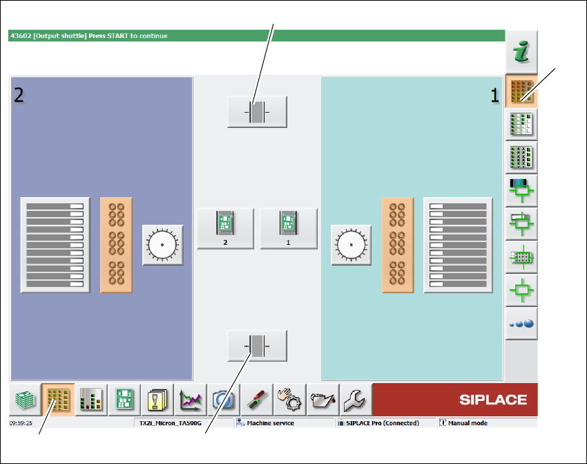
6.2 Shuttle extension on Station GUI
Each shuttle extension is controlled via the user interface of a machine. The machine on which
the shuttle extension is fitted will be shown as "this machine" in the various views.
Click Setup (1) icon from the station GUI tool bar.
Click Locations icon (3).
Fig. 6.2 - 1 Station software - "Setup" view
Click icon (2) to select the shuttle extension on output conveyor.
Click icon (4) to select the shuttle extension on input conveyor.
(1)
(2)
(4)
(3)
6 Operate the shuttle extension Assembly and Instruction Manual
6.2 Shuttle extension on Station GUI Shuttle Extension Edition 11/2018
70
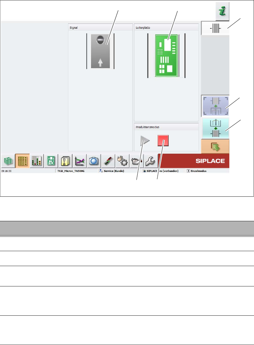
Fig. 6.2 - 2 Station software - "shuttle extension setup view
6
Key Description
1
Select the shuttle extension on output conveyor.
2
Select the shuttle extension on input conveyor.
3
Stops the automatic operation of the shuttle extension, single functions can be
executed.
4
Starts the automatic operation of the shuttle extension i.e. meaning that the boards
which arrive at the shuttle extension are transported through and then passed on to
the next machine, according to the configuration.
5
This shows the current state of the signal transmitter (laser light barrier). The LED
symbol shows whether there is a board in the shuttle extension or, in other words,
whether the signal transmitter (laser light barrier) has triggered.
(2)
(5)
(1)
(3)
(4)
(6)
(7)