00198320-02_UM_ShuttleExtension-DE-EN-ZH.pdf - 第105页
Assembly and Instruction Manual 1 Introduction Shuttle Extension Edition 11/2018 1.2 Overview 7 1.2 Overview 1.2.1 Shuttle extension at the out put side of a SIPLACE machine 1 Fig. 1.2 - 1 Shuttle extension input side on…
1 Introduction Assembly and Instruction Manual SIPLACE TX
1.1 Description Shuttle Extension Edition 11/2018
6
As an example, the following scenarios are possible:
– SIPLACE TX with dual conveyor (I-Placement) on a SIPLACE SX with dual conveyor (alter
-
nating mode).
– SIPLACE TX with dual conveyor on a printer or furnace.
– SIPLACE SX1/SX2 V2 with dual conveyor on a printer or furnace.
The shuttle extension is always fitted to a SIPLACE TX or SIPLACE SX1/SX2 V2. There is also a
shuttle extension available for the output side and a shuttle extension for the input side.
Assembly and Instruction Manual 1 Introduction
Shuttle Extension Edition 11/2018 1.2 Overview
7
1.2 Overview
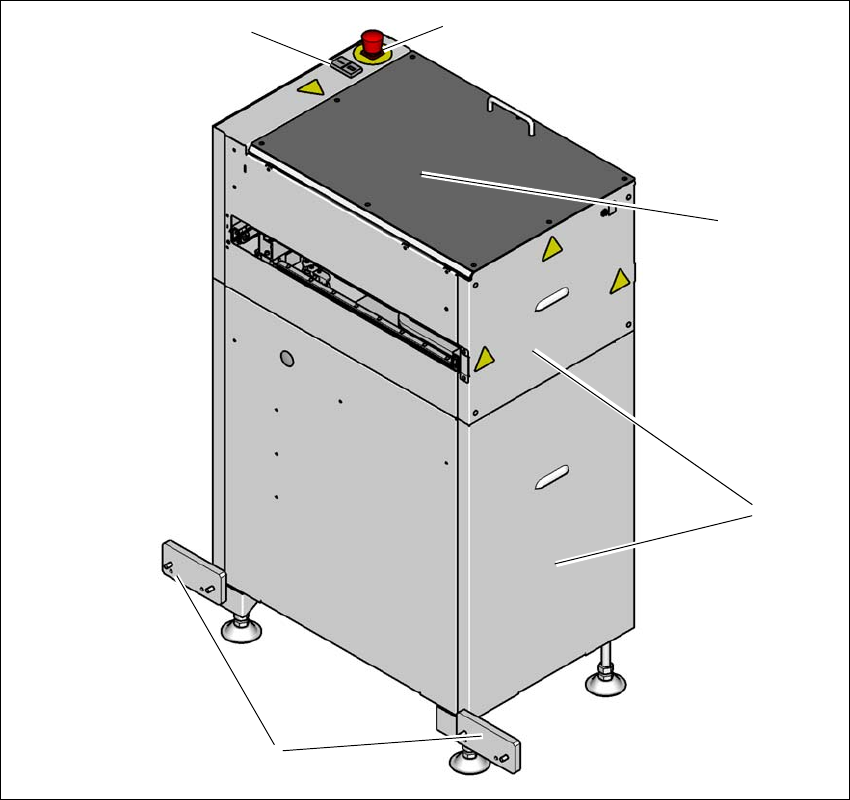
1.2.1 Shuttle extension at the output side of a SIPLACE machine
1
Fig. 1.2 - 1 Shuttle extension input side on the conveyor output of a SIPLACE machine
(1) Start and stop button
(2) EMERGENCY STOP button
(3) Top cover
(4) Side covers
(5) Connection fixtures on the conveyor output side of the SIPLACE machine
(1)
(5)
(2)
(3)
(4)
1 Introduction Assembly and Instruction Manual SIPLACE TX
1.2 Overview Shuttle Extension Edition 11/2018
8
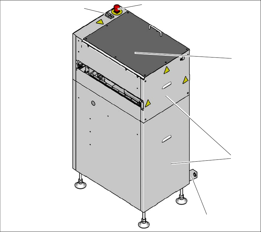
1.2.2 Shuttle extension on the conveyor input side of a SIPLACE machine
1
Fig. 1.2 - 2 Shuttle extension output side on the input side of the SIPLACE machine
(1) Start and stop button
(2) EMERGENCY STOP button
(3) Top cover
(4) Side covers
(5) Connection fixtures on the conveyor input side of the SIPLACE machine
(1)
(5)
(2)
(3)
(4)