00198320-02_UM_ShuttleExtension-DE-EN-ZH.pdf - 第138页
3 Assembly on the SIPLACE TX Assembly and Instruction Manual 3.3 Assembly kit and mechanical connection Shuttle Extension Edit ion 11/2018 40 3.3.1 Mechanical installation procedure Intermediate ledges on SIPLACE TX outp…
Assembly and Instruction Manual 3 Assembly on the SIPLACE TX
Shuttle Extension Edition 11/2018 3.3 Assembly kit and mechanical connection
39
3.3 Assembly kit and mechanical connection
A mechanical interface kit will be used to fix the shuttle extension into position. This mechanical
interface kit consists of 2x Intermediate Ledges, 4x Interface brackets, 4x ISO4762 M8 and 8x
ISO7380-2 M8 screws. The intermediate ledge is mounted onto the SIPLACE TX feet, while the
interface brackets are mounted on shuttle extension's body frame.
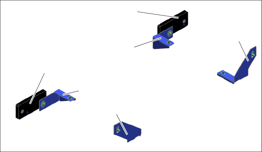
Fig. 3.3 - 1 Assembly kit for mechanical connection
(1) Intermediate ledge on SIPLACE TX output conveyor- right side
(2) Intermediate ledge on SIPLACE TX output conveyor- left side
(3) Interface bracket input shuttle extension- right side
(4) Interface bracket input shuttle extension - left side
(5) Interface bracket output shuttle extension - right side
(6) Interface bracket output shuttle extension - left side
(1)
(2)
(3)
(4)
(5)
(6)
3 Assembly on the SIPLACE TX Assembly and Instruction Manual
3.3 Assembly kit and mechanical connection Shuttle Extension Edition 11/2018
40
3.3.1 Mechanical installation procedure
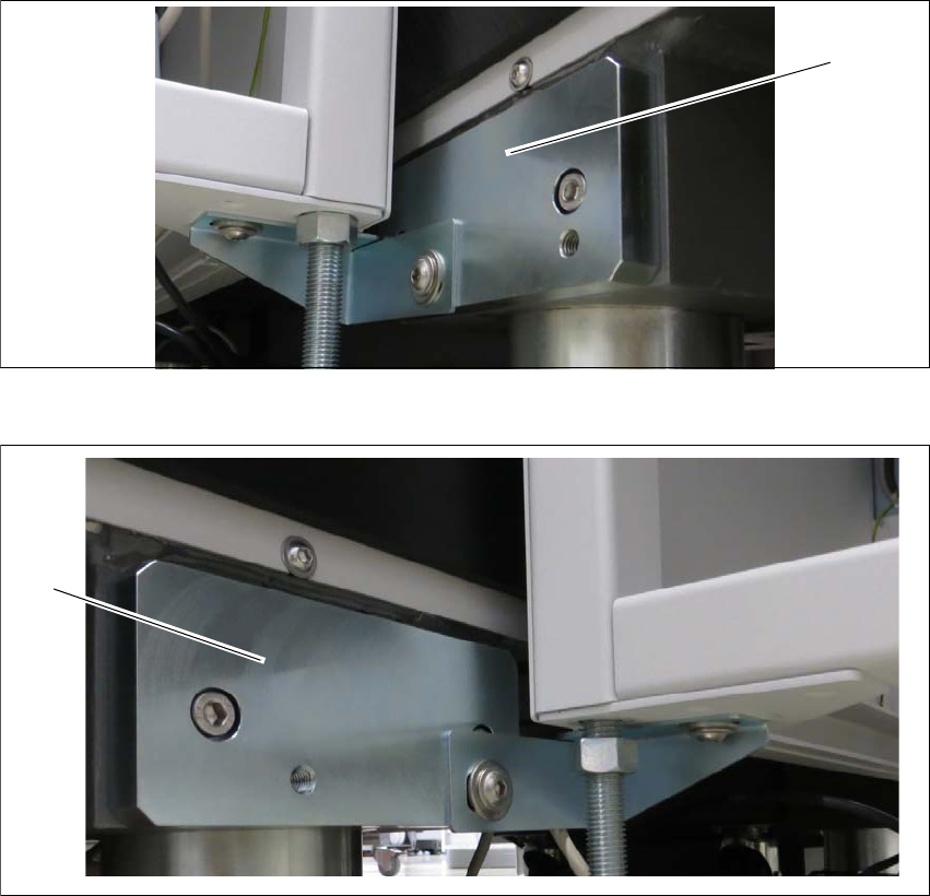
Intermediate ledges on SIPLACE TX output conveyor side 3
Fit the two intermediate ledges to the machine feet of the SIPLACE TX output conveyor side.
Fig. 3.3 - 2 Intermediate ledge - right side
Fig. 3.3 - 3 Intermediate ledges -left side
(1) Intermediate ledge input conveyor - right side
(2) Intermediate ledge input conveyor - left side
(1)
(2)
Assembly and Instruction Manual 3 Assembly on the SIPLACE TX
Shuttle Extension Edition 11/2018 3.3 Assembly kit and mechanical connection
41
General 3
Remove the four side covers from the shuttle extension. This gives you access to the fixtures
for the interface brackets and the electrical connection.
Move the shuttle extension to the SIPLACE TX.
Set the height of the shuttle extension, so that the PCB conveyor for the shuttle extension is
the same height as the PCB conveyor for the SIPLACE TX.
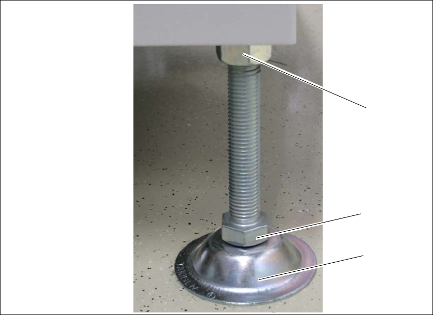
The shuttle extension stands on 4 feet.
Fig. 3.3 - 4 Presetting the height of the machine feet
(1) Top screw nut
(2) Bottom screw nut
(3) shuttle extensions feet
Turn the shuttle extension feet (3) with the bottom screw nut (2) so that the shuttle extension
has the PCB conveyor height of the SIPLACE TX.
Tighten the top screw nut (1), so that the machine feet are fixed into place.
Check the height of the shuttle extension and correct the height, if necessary.
(1)
(2)
(3)