00198320-02_UM_ShuttleExtension-DE-EN-ZH.pdf - 第140页
3 Assembly on the SIPLACE TX Assembly and Instruction Manual 3.3 Assembly kit and mechanical connection Shuttle Extension Edit ion 11/2018 42 Adjustment 3 Place a machine spirit level (measuring accuracy of 0.02 mm) ag…
Assembly and Instruction Manual 3 Assembly on the SIPLACE TX
Shuttle Extension Edition 11/2018 3.3 Assembly kit and mechanical connection
41
General 3
Remove the four side covers from the shuttle extension. This gives you access to the fixtures
for the interface brackets and the electrical connection.
Move the shuttle extension to the SIPLACE TX.
Set the height of the shuttle extension, so that the PCB conveyor for the shuttle extension is
the same height as the PCB conveyor for the SIPLACE TX.
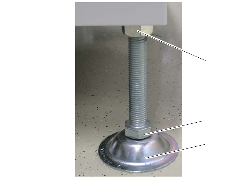
The shuttle extension stands on 4 feet.
Fig. 3.3 - 4 Presetting the height of the machine feet
(1) Top screw nut
(2) Bottom screw nut
(3) shuttle extensions feet
Turn the shuttle extension feet (3) with the bottom screw nut (2) so that the shuttle extension
has the PCB conveyor height of the SIPLACE TX.
Tighten the top screw nut (1), so that the machine feet are fixed into place.
Check the height of the shuttle extension and correct the height, if necessary.
(1)
(2)
(3)
3 Assembly on the SIPLACE TX Assembly and Instruction Manual
3.3 Assembly kit and mechanical connection Shuttle Extension Edition 11/2018
42
Adjustment 3
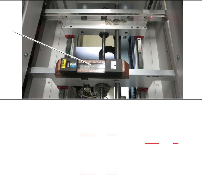
Place a machine spirit level (measuring accuracy of 0.02 mm) against the edge of the shuttle
extension PCB conveyor.
Fig. 3.3 - 5 Machine spirit level measuring accuracy of 0.02 mm) on conveyor rail
Use the machine spirit level (1) to align the shuttle extension in the X and Y direction, at the
four machine feet.
Unscrew the top nut (item 1 in fig. 3.3 - 4, page 41) with the help of an open-ended wrench.
Use the open-ended wrench to set the bottom nuts (item 2 in fig. 3.3 - 4, page 41) of all four
shuttle extension feet, so that the fluid in the machine spirit level does not deviate from its
zero point at the required conveyor height.
Check the required board conveyor height.
Tighten the top nuts (item 1 in fig. 3.3 - 4, page 41) to clamp all shuttle extension feet.
(1)
Assembly and Instruction Manual 3 Assembly on the SIPLACE TX
Shuttle Extension Edition 11/2018 3.3 Assembly kit and mechanical connection
43
Shuttle extension to SIPLACE TX alignment 3
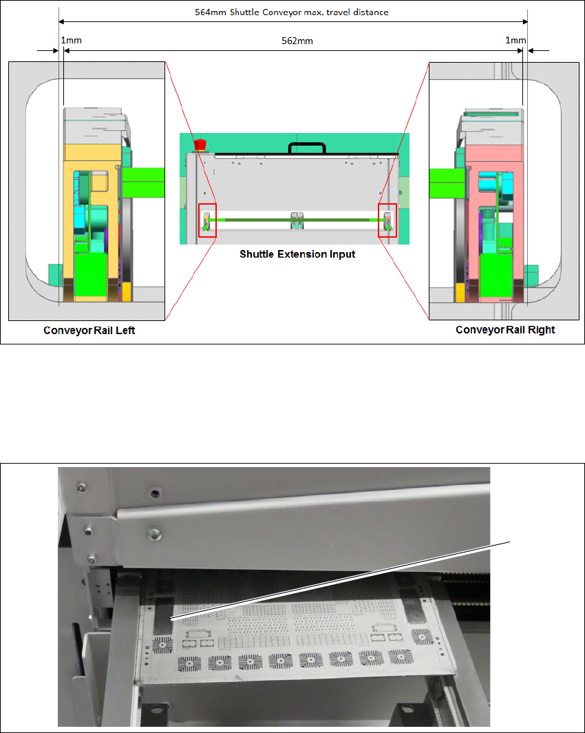
Fig. 3.3 - 6 Alignment position for shuttle extension
Shuttle conveyor rails to be positioned at 281 (1mm gap on each outer end) and fixed with
motor brake.
Align one of the shuttle conveyor rails (either left or right) to TX conveyor rail.
Fig. 3.3 - 7 Check PCB
Check rail position with the calibrated PCB.
Push a board through the PCB conveyor and check the transition point between the shuttle
extension and the SIPLACE TX.
(1)